Introduction
Development Quickstart
This page will help you get started with nexpaq. You’ll be up and running in a jiffy!
Here, you will find step-by-step instructions on using the nDK (nexpaq Developer’s Kit).
nexpaq introduces it’s first Developer Kit based System on a Chip!
Get to the Internet of Things by developing an environment with cross-platform compatibility between iOS and Android. Start your module idea with the nexpaq Developer’s Kit designed for companies, makers and hobbyists.
The nDK contains the necessary elements to develop a module application, such as the developer’s board (based on the nexpaq case) and two different kind of developer’s module boards (which will vary depending on the application).
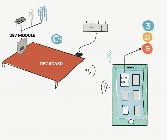

Communication Flow

nexpaq Hardware
Developer’s Board
The Developer’s Board has the same hardware features as the nexpaq case.
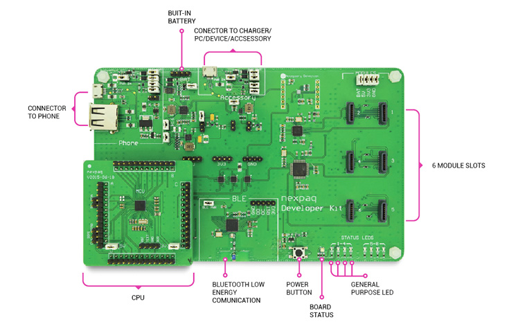
The Developer board features:
- 6 nexpaq female module connectors (see PCB and nexpaq connector Specs for a complete definition)
- USB accessory to connect to an external device
- USB 2.0 for wire phone communication
- Bluetooth Low Energy communication – BLE (wireless phone communication)
- MSP430F5528Microcontroler
- Ultra-Low-power 16-bit microcontroller with a 12-bit Analog to Digital Converter (ADC) with window comparator
- 2 Universal Serial Communication Interfaces
- 128 Kb of Flash Memory
- Full-Speed Universal Serial Bus
- Hardware Multiplier that supports 32-bit Operations
- Operating Voltage: 5V
IMPORTANT! If your Dev Board is v2016-02-01 or below, you might need to check the Dev Board update (v2016-02-01) or bellow documentation
- Technical specs
- Microcontroller Board based on MSP430F5528
- Operating Voltage: 5V
- Bluetooth Low Energy communication (BLE) – CC2541F256RHAR
- 1 nexpaq female module connectors (SPI and USB communication – see Connector and PCB specs for a complete definition)
- USB accessory to connect to an external device
- USB 2.0 to power (Power USB)
- USB 2.0 for Device (PC USB)
- 3 Status LED
- Download interface Pins to MSP
- UART monitoring communication (Debugger mode for MPS)
- SPI connector analyzer test Pins

MSP Module
The module has a firmware configuration that allows communication between theMSP Module and the phone. It also allows the module and the developers board to interact. This means that the developers don’t need to program low-level drivers for communication. This IC contains a micro-controller to program or create a module capable of interacting with a phone, the environment or control and connect to other devices. Once the application is developed it can be used in the nexpaq module case, which has the module gateway to fit in Developer’s Board, nexpaq phone case and batpaq.
All nexpaq modules use MSP430G2553 micro-controller, which allows nexpaq Communication Network (communication between module, case and phone tile). The board is composed of accessible pins to connect to sensors, actuators, other circuits and external devices.
MSP Module features:
- 16 accessible pins
- 2 device pins for SPI gateway communication (JTAG pins to program development and Flash programming only)
- 8 accessible supply pins (3.3V, 5V and battery)
- nexpaq male module connector
- MSP430G2553 microcontroller:
- Ultra-Low-power Consumption 16-bit MSP430 with a 10-bit Analog to Digital Converter (ADC) with internal reference
- On-Chip comparator
- Universal Serial Communication Interface
- 16Kb of Flash Memory
- 512 bytes of RAM
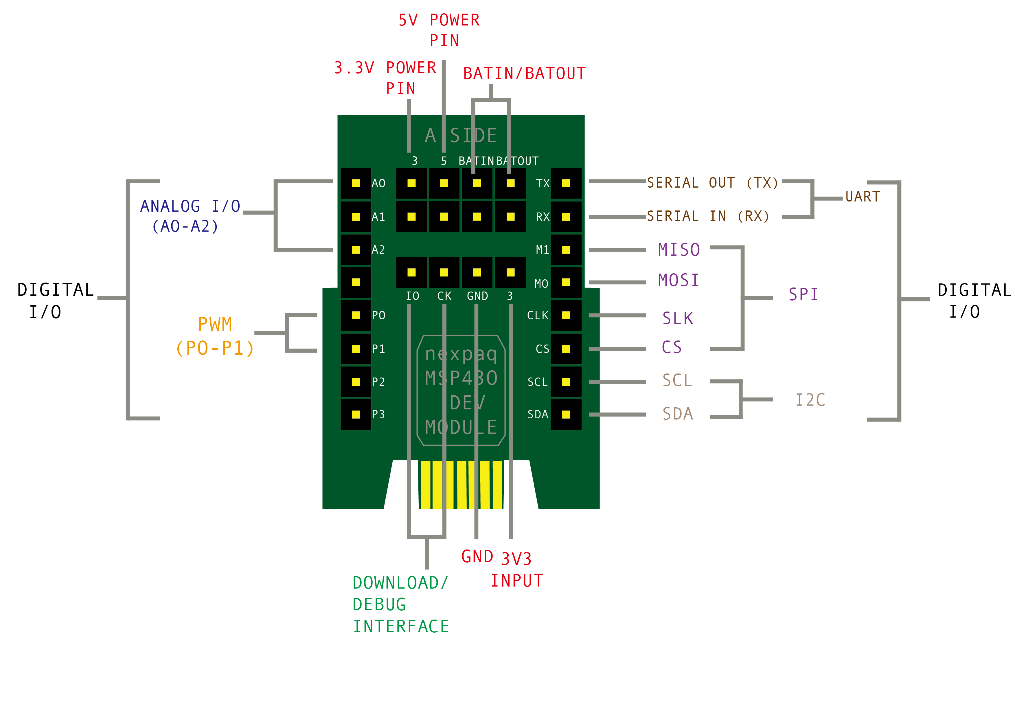
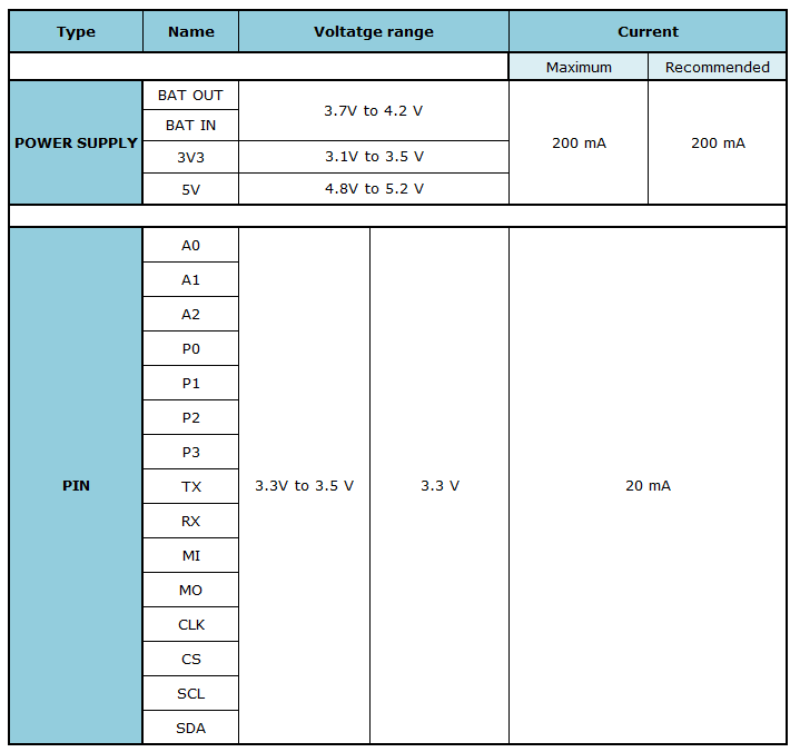
See information about pin ratings on the table below:
Pin configuration can be modified by firmware using GPIO library according to the following table:
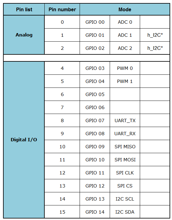
(*)I2C is supported for both software and hardware libraries, for hardware I2C use pins according to the table. For SPI and UART, use only software libraries
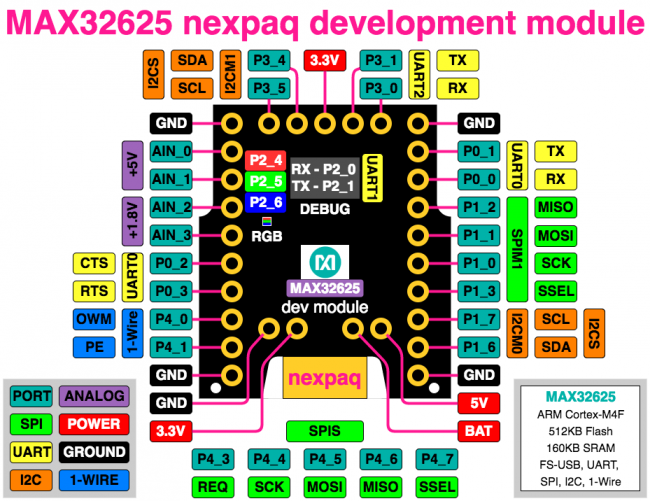
MAX32625 Module
The MAX32625 nexpaq development module is a tool enabling the development of new modules for the nexpaq system. It includes everything needed to connect to the nexpaq gateway and provides access to a variety of different interfaces for expansion to anything you can imagine. This brings a new level of freedom to your mobile device.
Features
- MAX32625
- 96MHz ARM Cortex M4F
- 160KB SRAM, 512KB Flash Memory
- UART, SPI, I2C, 1-Wire Serial Interfaces
- 10bit ADC
- nexpaq Interface
- nexpaq card edge connector
- nexpaq interface library
- Expansion Connectors
- Analog, PWM, I2C, SPI, UART I/O headers
- 3.3V, 5V, BAT and GND Power headers
- SWD Programming/Debug Header
- mbed Online Developent Environment
- no installation required
- driverless drag-and-drop programming
- On Board Peripherals
- Red/Green/Blue LED
Overview
At the heart of the MAX32625 nexpaq development module is the MAX32625 ARM Cortex M4F micro-controller. The MAX32625 manages the connection to the nexpaq gateway and provides a rich set of interfaces to connect with whatever peripherals you will be using. Code for the MAX32625 is developed with the online tools at the mbed developer site: developer.mbed.org There you will find libraries and examples to speed firmware development.
Port Configuration Modes
The ports of the MAX32625 can be configured to access several different functions through each port pin. A table of the functions available at the pins is included here.
| Pin | Label | Functions | ||||
|---|---|---|---|---|---|---|
| AIN_0 | A0 | ADC ch 0 | ||||
| AIN_1 | A1 | ADC ch 1 | ||||
| AIN_2 | A2 | ADC ch 2 | ||||
| AIN_3 | A3 | ADC ch 3 | ||||
| P0_0 | RX | UART0 RX (A) | UART0 TX (B) | TMR0 | PT0 | GPIO |
| P0_1 | TX | UART0 TX (A) | UART0 RX (B) | TMR1 | PT1 | GPIO |
| P0_2 | P0 | UART0 CTS (A) | UART0 RTS (B) | TMR2 | PT2 | GPIO |
| P0_3 | P1 | UART0 RTS (A) | UART0 CTS (B) | TMR3 | PT3 | GPIO |
| P1_0 | SCK | SPIM1 SCLK | SPIX SCLK | TMR2 | PT8 | GPIO |
| P1_1 | MOSI | SPIM1 MOSI | SPIX SDIO0 | TMR3 | PT9 | GPIO |
| P1_2 | MISO | SPIM1 MISO | SPIX SDIO1 | TMR4 | PT10 | GPIO |
| P1_3 | CS | SPIM1 SS0 | SPIX SS0 | TMR5 | PT11 | GPIO |
| P1_6 | SDA | I2CM0 SDA | I2CS SDA (A) | TMR2 | PT14 | GPIO |
| P1_7 | SCL | I2CM0 SCL | I2CS SCL (A) | TMR3 | PT15 | GPIO |
| P2_0 | DBG_RX | UART1 RX (A) | UART1 TX (B) | TMR4 | PT0 | GPIO |
| P2_1 | DBG_TX | UART1 TX (A) | UART1 RX (B) | TMR5 | PT1 | GPIO |
| P2_4 | Red | TMR2 | PT4 | GPIO | ||
| P2_5 | Green | TMR3 | PT5 | GPIO | ||
| P2_6 | Blue | TMR4 | PT6 | GPIO | ||
| P3_0 | P3/0 | UART2 RX (A) | UART2 TX (B) | TMR0 | PT8 | GPIO |
| P3_1 | P3/1 | UART2 TX (A) | UART2 RX (B) | TMR1 | PT9 | GPIO |
| P3_4 | P3/4 | I2CM1 SDA | I2CS SDA (B) | TMR4 | PT12 | GPIO |
| P3_5 | P3/5 | I2CM1 SCL | I2CS SCL (B) | TMR5 | PT13 | GPIO |
| P4_0 | P2 | OWM IO | TMR2 | PT0 | GPIO | |
| P4_1 | P3 | OWM PUE | TMR3 | PT1 | GPIO | |
MAX32625NEXPAQ Product Page
PCB and nexpaq connector Specs
PCB Specs
- Power supply and regulator for the MSP
- Module interface: nexpaq gateway
- Download interface: Program and debug interface
The connector and download interface have a footprint encoded. An Altium library is also provided, which includes the nexpaq connector, download interface, and layouts. In order to print the circuit board, PCB dimensions must be accurate and therefore match with connector’s and housing dimensions (see specifications in the detailed drawing).
nexpaq module connector specs
Power:
- 5V o 3.3V
- Power line (BAT+) for battery or other energy modules which accept or provide3.0V to 5.25V
Communication:
- High-Speed SPI (up to 1 MBit/s) which can be slowed down for slower modules
- High-Speed USB 2.x (up to 480 Mbit/s) which can be slowed down for slower
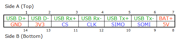
Pin specifications
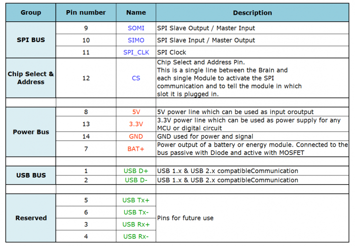
PCB Layout specs for the Connector
5V BUS:
- It is the power bus for the case, phone, and other modules. There is a high current through it, so the track width should be as wide as possible. There may be limited space because of the PCB size however it is recommended that track width is 40mil ~ 80mil.
BAT+ BUS:
- It is the power bus for the case, phone, and other modules. There is a high current through it (because of the battery capacity and discharge current) therefore, the track width should be as wide as possible. Space may be limited due to the PCB size however it is recommended that the track wide is 40mil ~ 80mil.
3V3 BUS:
- It is a power bus that reduces the wire impedance. It is recommended that the track width is 40mil ~ 60mil.
USB:
- It is a differential signal line, so it is should be routed accordingly. The differential impedance resistance is 90 Ohm.
Observations: Note that P3.0 in MSP430 is not an accessible pin as it is used as a control pin for 5V.
Maximum & Recommended Current & Voltage
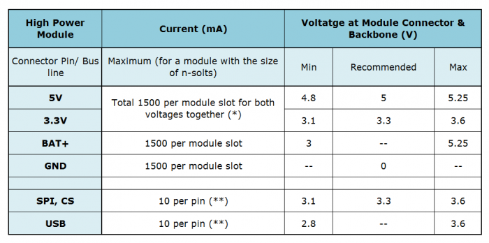
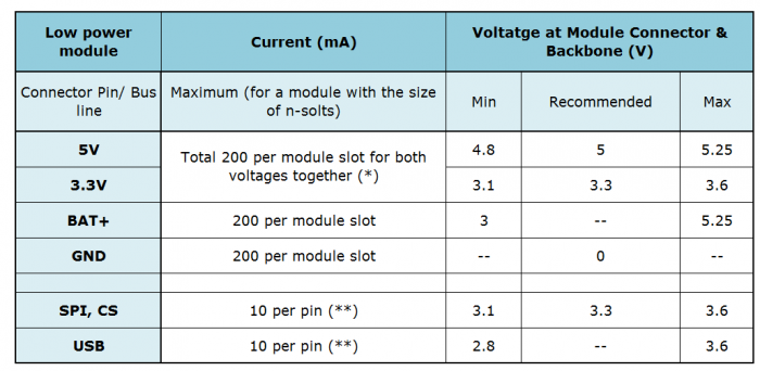
(*): Maximum 2A per each connector pin. Multiple connectors need to be used if the multi-module needs more pins. Below the max number of pins, it can use a single connector to get the maximum current reserved for all slots used by that module.
(**): A multi-module require usually just one SPI communication and if necessary one USB communication. If a multi-module requires multiple SPI and/or USB communications then additional connectors can be used. However, these different connectors cannot connect with each other.
Module Layout and Schematics
MSP PCB files
- Bare minimum PCB components for MSP430
- Altium PCB files for 12 nexpaq modules
MAX PCB files
HOUSING
Getting Started
nexpaq application with custom tile
- Power a Developer’s Board to be able to scan it and click on ‘Find Devices’
- Open up nexpaq application and turn on the Bluetooth on the phone
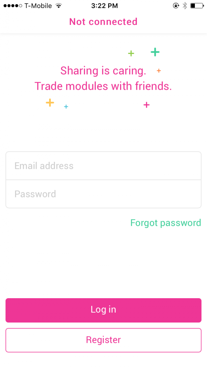
- Login in / Register on the nexpaq application
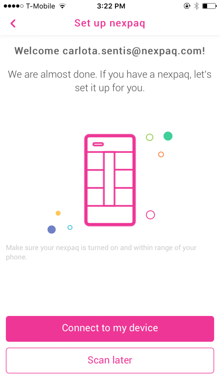
- After logged in, select the developer board by clicking on it (a right click appears when the board is selected) and Clik on Connect
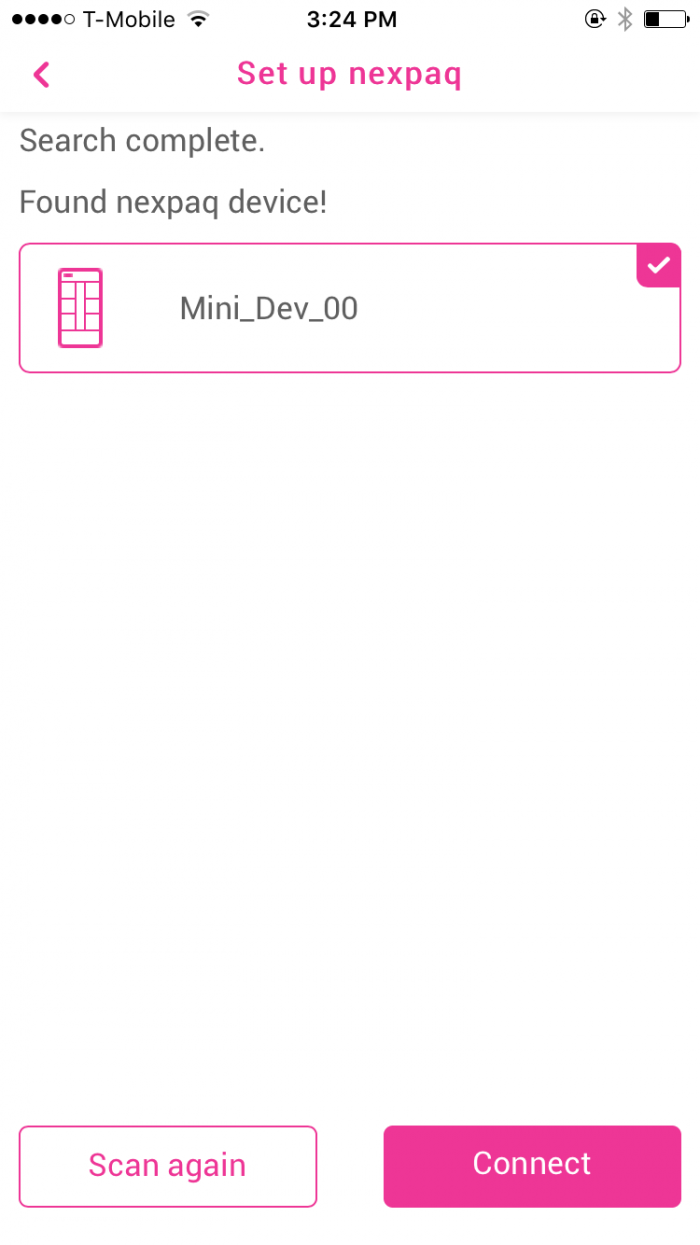
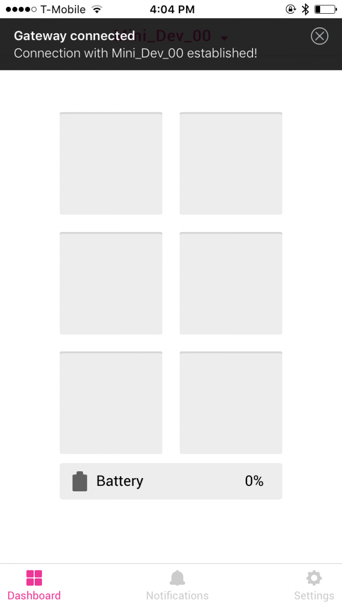
- If the connection between the Mini Dev Board and the phone application is successful a message is displayed at the top of the application.
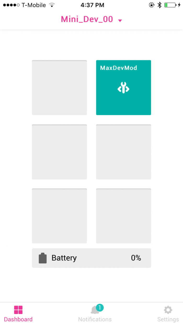
- If any tile is manually added the default developer tile is displayed
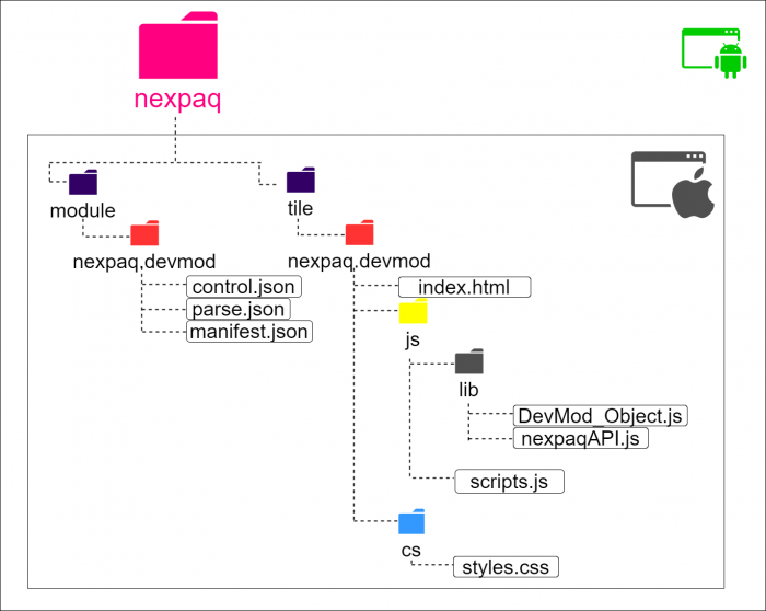
Uploading Tiles for iPhone
Step 1)
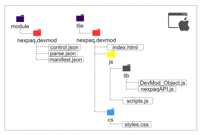
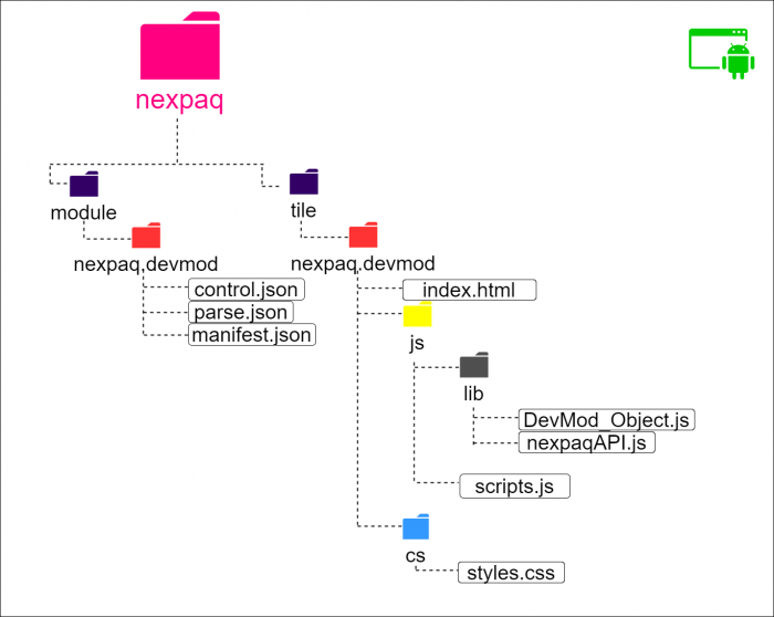
- Create 2 folders labeled “module” and “tile”
- Inside both folders a “nexpaq.devmod” folder should be created.
- Inside “module”, and inside ”nexpaq.devmod” folder, Control and Parse files should be placed
- Within “tile” and “nexpaq.devmod”, index.html file, css and js folders should be placed.
- Next open up iTunes and connect your iPhone.
- Select your device within iTunes from the top bar.
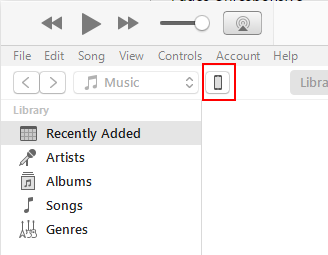
- Under the Settings tab on the left pane, select “Apps”.
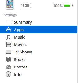
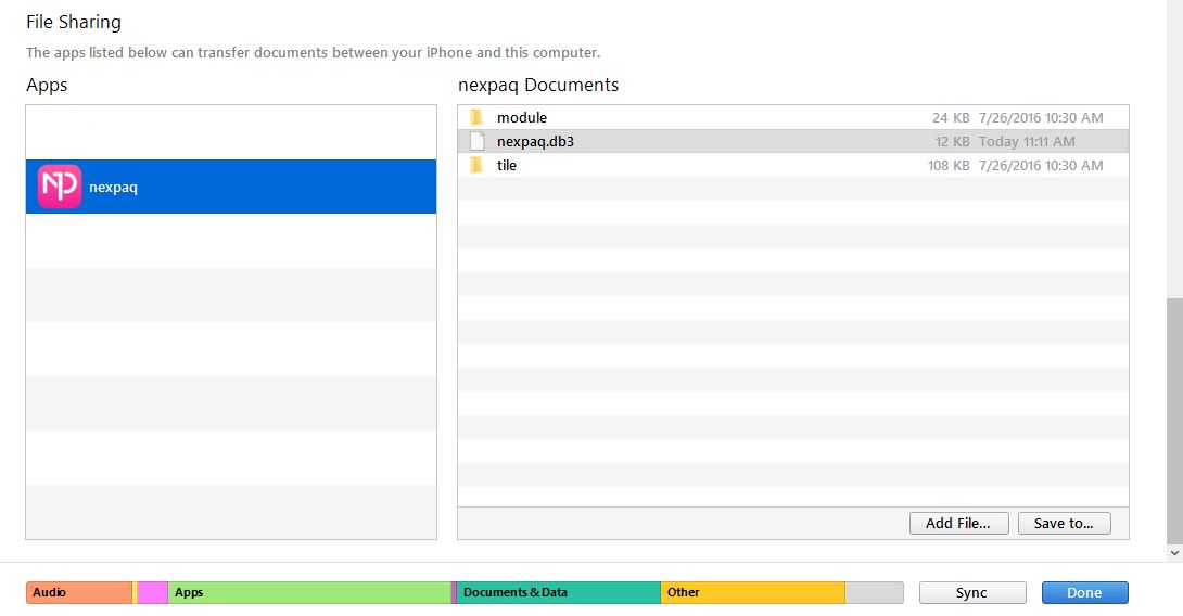
- Scroll down to the bottom to “File Sharing” page.
- Select nexpaq and drag and drop both folders, “module” and “tile”, in the right window. (make sure nexpaq is highlighted on the left window when doing this)
Uploading Tiles for Android
Step 1)
- Connect Android phone to a PC
- Find the phone in File Explorer
- Create a folder at phone’s main directory named nexpaq (Phone/nexpaq)
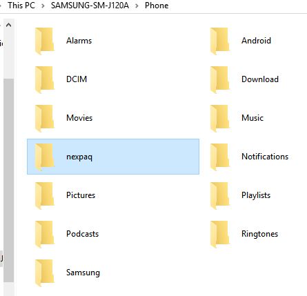
- Within “nexpaq”, create a “module” folder and “tile” folder.
- Inside both folders a “nexpaq.devmod” folder should be created.
- Inside “module”, and inside ”nexpaq.devmod” folder, Control and Parse files should be placed
- Within “tile” and “nexpaq.devmod”, index.html file, css and js folders should be placed.
- Open nexpaq application on an Android phone
- If you haven’t already, add the Tile (unzip the tile folder and copy ’tile’ and ‘module’ folders as explained above)
- Connect all hardware and run the module from the Tile.
Flashing the MSP module
In order to program the MSP module, the following hardware is required:
- TI Launchpad
- nexpaq Developer’s board
- Developer’s MSP module
- Install the CCS IDE from TI, CCS V5.5 version (or above*), 16K FLASH limitation is suitable for nexpaq modules.
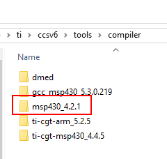
* If versions above V5.5 are installed, the compiler labeled msp430_4.2.1 should be added at the CCS compiler folder
- Go to TI folder at the Hard Drive
- ti > ccsv6 > tools > compiler and copy the msp430_4.2.1 compiler
- By installing CCS, drivers for LaunchPad are automatically installed.
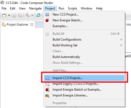
- Import module project at Code Composer Studio.
- All CCS nexpaq MSP430 projects should include nexpaq mdk files (.h and .lib)
Connect the LaunchPad using the included USB cable to a Windows enabled PC. The driver installation starts automatically. If prompted for software, let Windows automatically install it. This is possible only if CCS is already installed.
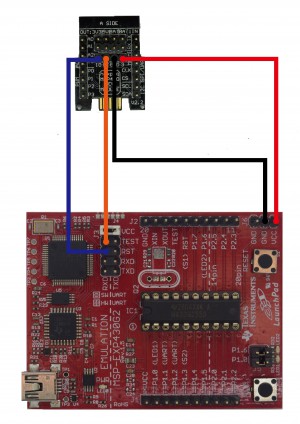
- Connect both devices as seen in the image below.
- Take all jumpers off the LaunchPad but KEEP the jumper at VCC pins from EMULATION to MSP-EXP430G2
- MSP pins from debug and program interface to Launchpad pins debug and program interface (EMULATION part)
MSP MODULE – LAUNCHPAD
3V3 – VCC
GND – GND
IO – RST
CK – TEST
- Before uploading the program to the MSP make sure the debug options are not set to “Erase the main memory” (bootloader)
- Do right click on current project and select Properties > Debug > MSP430 Properties > Erase Options and select Replace written memory locations, retain unwritten memory locations
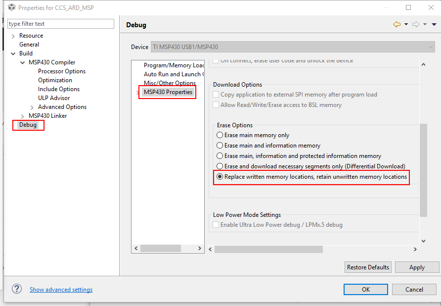
Now the MSP is ready to be flashed !
- Click on the “Debug” button as shown below:
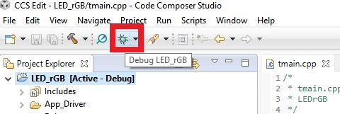
- The flashing is complete when the “Loading complete” message is displayed.
- nexpaq connector has two sides. Its VERY IMPORTANT to insert the module to the case facing the pins out of the hub (so its easier to attach the wires to a breadboard or another hardware)
- After attaching the module to Dev Board, it should be detected by the nexpaq application.
- Dowload the nexpaq application
TIP :
NOTE:
A) If the main memory is accidentally erased, no worries. Follow the steps listed at Dev Board update (v2016-02-01) or bellow document under Reference tab to upload it again.
B) Using CCS Debug To use the MSP module at CCS Debug mode, PC registers should be changed:
- Press the suspend button
- At the memory Browser type 0XEFFE
- Look for the corresponding vector
- Type the corresponding value in PC registers
- Press resume button
Code Development
Tile Development

Nexpaq interface development for custom modules is based on a Multiplatform Web Interface. To generate suitable tile (also called module interface) for all platforms, languages used are HTML 5, CSS and JavaScript.
- The tile runs as is located in a local server.
- An internet connection is required to run any tile for first time. After downloading the tile, it can be used without an internet connection given it doesn’t perform any other functions such as saving results to the cloud, sending them or other functions that would require an internet connection.
Throughout the documentation we will define upstream and downstream as follows:
- Upstream: Communication from Firmware to Tile (Module Interface).
- Downstream: Communication from Tile to Firmware.
- Install any text editor for code, markup and styles (such as Sublime Text and Atom.)
- Download nexpaq application on your device.
- Download Tile, the bare minimum of code needed to run the Developer Module phone application.
- If on iOS, after the nexpaq installation go to Settings > General > Device Management, select nexpaq and “trust”.
- If on Android, you will be guided through process of installing the app.
- Stylesheet document that defines the presentation of an HTML document.
- It describes how elements are rendered on screen, paper, or in other media.
To see a quick CSS tutorial, click here.
- Basic HTML markup is used in this part setting different tags.
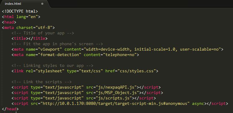
- index.html includes CSS and JS links to describe the document contents. The name of the tile is defined here as well.
To see a quick HTML tutorial, click here.
- Module’s function code must be included in “.js” files.
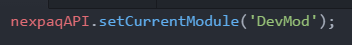
- The developer module must be set at the begining of the document via the setCurentModule function.
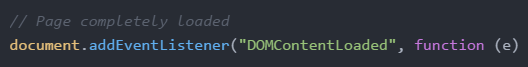
- An event listener function is used to make sure that the tile is completely loaded.
- This is an event handler function taken from the nexpaqAPI.js.
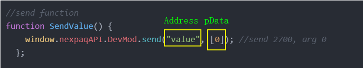
Sending data from the tile to the developer module:
- control.json file is needed when using downstream communication (see Control, Parse & Manifest under Code Development for details)
- send function has two attributes, Address and pData
- Address corresponds to the string name given at the control.json file for the correpsonding address
- pData is the argument for address. The length of the array is from 0 to 53 elements and each element holds integer values (from 0 to 255).
Receiving data arrays sent from the developer module to the tile:
- parse.json file is needed when using upstream communication (see Control, Parse & Manifest under Code Development for details)
- The data array can be accessed by using last_data.”fun” (where “fun” corresponds to function’s name given at parse.json.
- In order to save the data into a variable, the following format can be used:
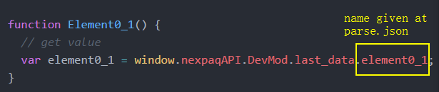
- If data array element is not defined, the value will be set as “undefined”.
To see a quick JavaScript tutorial, click here.
KEEP IT IN MIND
- nexpaqAPI.js must be included in order to communicate with the native application and firmware.
- DevMod_Object.js is an extension of the nexpaqAPI.js library which allows to define module’s function such as send and receive (include this file to use send and receive function).
Recommendation Locate styles.css and scripts.js files inside css and js folders.
Control, Parse & Manifest
- Control, Parse and Manifest are json files used to transmit data objects
- These files are nedeed to establish the communication between the nexpaq application and the firmware
- control.json is used to send data from the application to the firmware.
- If no information needs to be transmitted from the tile to the hardware, the control file may be omitted.
- It has two attibutes, name and cmd (command)
Attributes
- name: name for the command.
- name CAN be changed. The name must be the same in both control.json and the send function at scripts.js
- cmd: command number, converted to decimal value (range from 39-0 to 39-255. It corresponds to 0x2700 to 0x27FF ). This parameter CAN’T be changed.

- control.json is ready to use as all commands are established.
- It includes address information (from 2700 to 27FF) and argument values.
- It converts tile data to JSON string to control the target hardware.
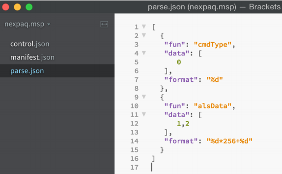
- parse.json is used to send raw data from the firmware to the application.
- If no information needs to be transmitted from the hardware to the tile, the parse file may be omitted.
- It has 4 attributes: fun, data, format and state
Attributes
- fun: function’s name
- name given at parse.json is used to access data array at scripts.js

- name given at parse.json is used to access data array at scripts.js
- data: indexes in array of data received from firmware
- Array elements corresponding to pData at np_api_upload function.
- “data” can access elements from 0 to 53 byte
- Each element is 8 bit length

- Data sent upstream via np_api_upload function has 2 element on the image above. Parse file (also on picture avobe) takes element 0 and 1 and stores both at “element0_1” array
- format: each element must be in a numeric format.
- %d (for digit) is the format supported
- The format needs to be definded for every element
- The image bellow shows how to give the format for two elements.
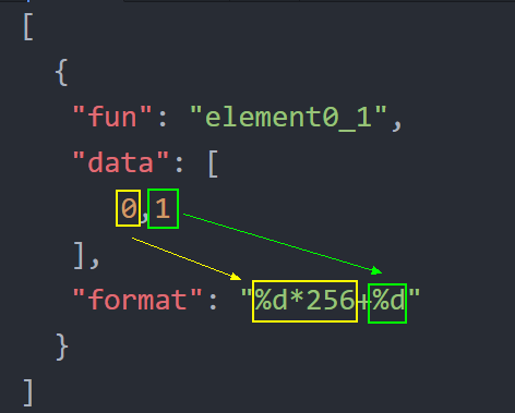
- If data resolution is bigger than 8 bit then two element of the array are needed. In the image above the first element is multiplied by 256 in order to have the correct value.
- state: variables taken according to indexes in data attributed converted to HEX string and one HEX string can be mapped to another string
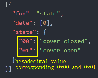
!IMPORTANT:
- The parse file must contain the same number of indexes sent from the firmware. The indexes can be stored at different arrays. See image b`ellow as example:
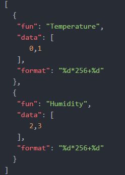
- Temperature and Hummidity are stored in two diferent arrays, form the firmware a 4 byte array is sent.
- The parse file must contain the same number of indexes sent from the firmware. The indexes can be stored at different arrays. See image b`ellow as example:
- format and state attibutes can’t be used together.
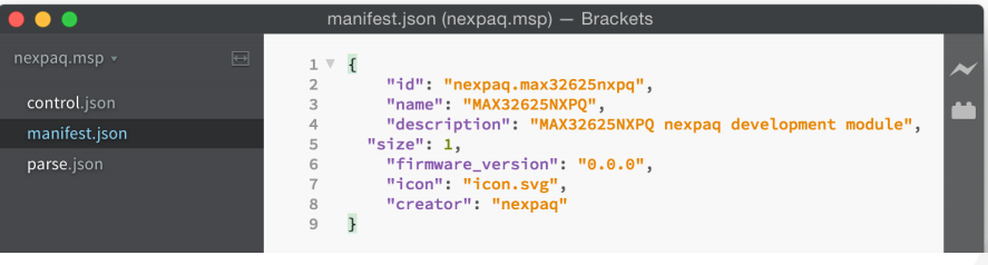
- manifest.json is used for module description
- It is requiered for every module and tile
Attributes
- id: id given will be used as folder name under module and tile folders.
- id format: creator id.item id
- name: assign a name for the corresponding module
- description: brief description on module’s application
- size: amount of slots that the module is taking (1, 2 or 3)
- firmware_version: related to module’s firmware version
- icon: icon for nexpaq application.
- creator: module creator
MAX Firmware Development
Follow steps listed at mbed platform for MAX32625
Information for Flash and RAM memory usage
Flash and RAM of MAX module application ( local compiler )
- INFO_ROM (rx) : ORIGIN =
0x0000E000, LENGTH = 0x00002000 /*Information: uuid, etc. */ - FLASH (rx) : ORIGIN =
0x00010000, LENGTH = 0x00070000 /*APP*/ - SRAM (rwx) : ORIGIN =
0x20003100, LENGTH = 0x00024F00 /*APP*/
Flash and RAM of MAX module bootloader ( local compiler )
- FLASH (rx) : ORIGIN =
0x00000000, LENGTH = 0x0000E000 /*BOOTLOADER*/ - SRAM (rwx) : ORIGIN =
0x20000100, LENGTH = 0x00003000 /*BOOTLOADER*/
MSP Firmware Development
CODE EXPLANATION
Write the main code at tmain.cpp file:
- When using downstream comunication (data sent from the tile to the module), specify the MDK function parameters. The MDK_REGISTER_CMD function requires two parameters:
- command: From 2700 to 27ff
- function: function’s name
- void_np_api_setup()
- For downstream comunication: Keep if statment for communication check. Set MDK_REGISTER_CMD function’s length according to number of commands used.
- Initialize pins and set pin modes and values
- Setup loop will just run one time after powering the MSP
- Set code’s version (optional)
- void_np_api_loop()
- main loop, loops consecutively
- This loop runs all the time while the MCU is not in sleep mode or has a stop condition
- After sending the parameter through np_api_upload(), if the data has been stored successfully it returns 0. If not, it returns 1.
- void_np_api_start()
- Start module’s function
- void_np_api_stop()
- Stop module’s function
- Use np_api_upload(2800, pData, length) :
- 2800 is corresponding command use to send data from MSP to Tile.
- pData is data send from MSP to Tile. Array’s element is 8 bit (1 byte) length
- Length of the array can be 0~53 byte.
- np_api_upload(2800,pData,length) can be used in void np_api_loop() to send values constantly to the app
Write module’s function at t_my_app.c file. This function must be according to the settings from MDK_REGISTER_CMD function at tmain.cpp (same name and corresponding command)
- void my_function_CMD_27XX() at t_my_app.c contains instructions to interpret modules’s function to perform the corresponding task send from the tile
- It can be renamed but the name must be the same at t_my_app.c, t_my_app.h and tmain.cpp
- range: from 0x2700 to 0x27ff
- value: 16 bit (2 byte)
Function parameters:
- pData: The element of the array is 8 bit (1 byte),
- len: the length of the array can be 0~53 byte (holding values from 0 to 255).
! Recommendation: for command value use odd numbers, for command response use even numbers.
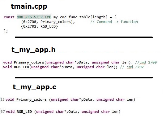
!IMPORTANT : Function’s name must be the same at tmain.cpp, t_my_app.c and t_my_app.h. See example:
KEEP IT IN MIND
- Include nexpaq mdk np_module_mdk_v1.h and np_module_mdk_v1.lib at any project. This library has protocols needed for board – module comunication.
- np_api_loop() doesn’t run all the time when using np_api_pm_automode_set(). Automode will select sleep mode any time
- For information on pin map configuration open NCN_GPIO library files or on check the tables above
- Project Explorer in CCS contains all information about the project (such as libraries, drivers and mdk).
The nexpaq module – gateway comunication is via SPI. Even thought, the USB comunication can be used. See table bellow:
Information for Flash and RAM memory usage
Flash and RAM of MSP module application
————— ——– –
RAM 0x00000210 0x000001f0 0x0000017b 0x00000075
FLASH 0x0000c000 0x00002fe0 0x00000d9f 0x00002241
Flash and RAM of MSP module bootloader
MSP Resources
PWM – LED rGB
In this resource, you will experiment on how to make a LED module simple application. General ideas behind sending A/D signal through the mobile cross-platform application will be shown.
By following this example with nexpaq Developer Kit you will learn:
- How to develop a nexpaq firmware application
- How to create a simple module application
- How to communicate the hardware and the Tile
Throughout the documentation we will define upstream and downstream as follows:
- Upstream: Communication from Firmware to Tile (Module Interface)
- Downstream: Communication from Tile to Firmware
- 1 x Breadboard
- male – female connectors and jumper wires
- 1 x LED RGB WS2812B
- 3 x 1k ohm ¼ W 1% resistor
- 1 x nexpaq Dev_Module
- 1 x nexpaq Developer’s board
- 1 x MSP-EXP430G2 LaunchPad
- 1 smartphone
- CCS IDE
- Any text editor (such as Sublime Text and Atom)
- nexpaq application

- Click on LEDrGB to download the CCS code
- Flash the module with LEDrGB code using TI LaunchPad (Follow procedure listed at Flashing the MSP module under Getting Started)
- Main code is included at tmain.cpp file
- A driver is used as a PWM software function (RGBLedByPwm.c/ .h)
- A function from the MDK – MDK_REGISTER_CMD – is used for downstream communication. It requires two items:
- command: From 0x2700 to 0x27ff
- function: function’s name
- For this example, two commands from the function are used. One for setting primary colours and another one to set all RGB colours.
- The definition on MDK_REGISTER_CMD function must be declared at tmain. For LEDrGB two commands are used for (then length is two)
!IMPORTANT : When using downstream communication function’s name must be the same at tmain.cpp, t_my_app.c and t_my_app.h.
- t_my_app file is used to specify downstream communication and module’s function. pData is an array sent from the Tile. len parameter gets the length of the array.
- According to each value on pData element, LED will take a different status. For example, the red color is assigned when pData equals to 1 (details from app side will be seen later).
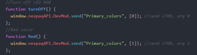
- Command 0x2700 (renamed as Primary_colors) is used to assign primary colors and white to the LED. Also to turn it off
- Command 0x2702 (renamed as RGB_LED) sets any RGB color
- Once the MSP module is flashed, set up the RGB LED in a breadboard as shown in the image bellow
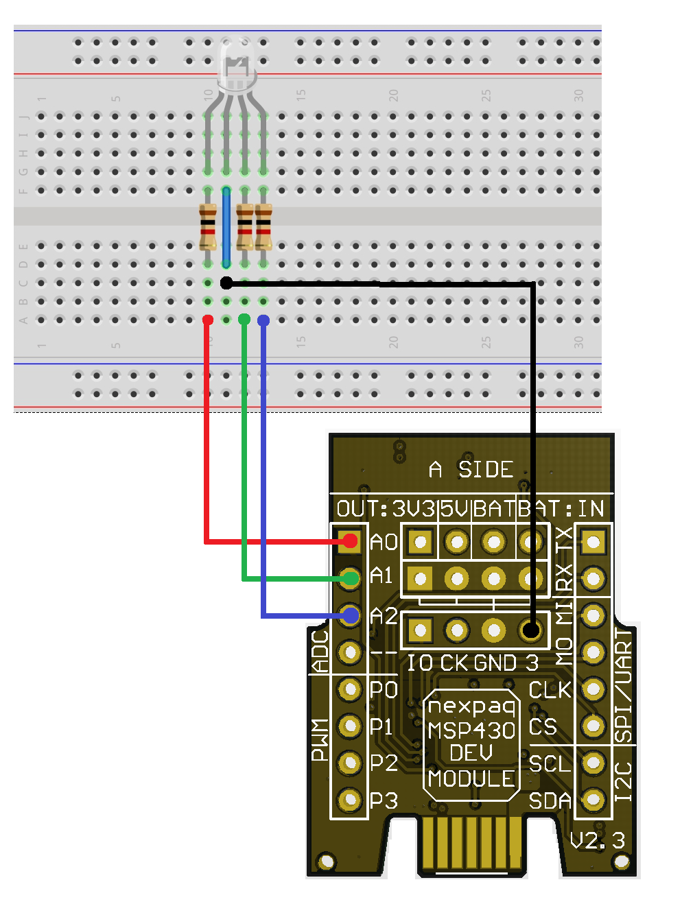
- After everything is connected you can plug the chip into the board, with the pins facing outwards. If they point inward, the Developers board won’t be able to connect to the MSP.
- Download nexpaq application
- Download LEDrGB Tile
nexpaq custom module applications include four different files:
- Scripts (JavaScript files)
- Styles (css files)
- Index (html file)
- img (images)
Check under Tile Development for detailed documentation
- Scripts files include JavaScript files for Tile function, API and DevMod_Object. nexpaqAPI and DevMod_Object are library files. Module function is defined at scripts.js.
- First of all, MSP module must be set

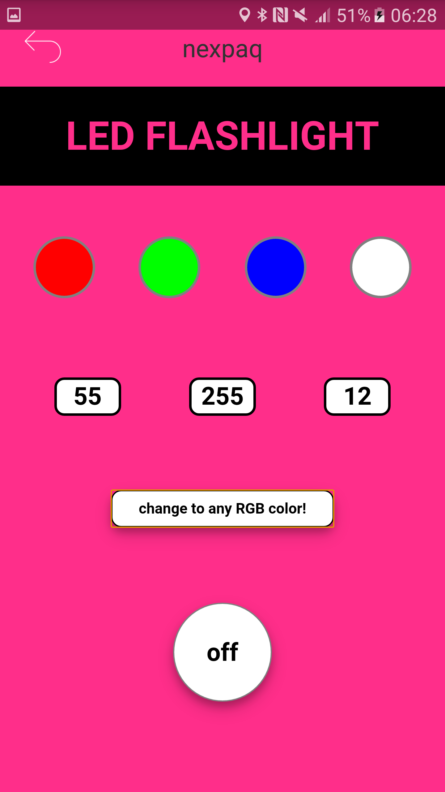
- Each color is defined as a function, and each function sends a different parameter to the native app. To send data a function from nexpaqAPI is used and it must include two parameters: address and pData. Two addresses are set in the control file, one for setting the primary colors (also to turn off or light white) and the other one for setting any RGB colors. In order to turn off the LED, primary colors address is used with argument 0 (pData).
- To send primary colors function the same address is used but with different arguments.
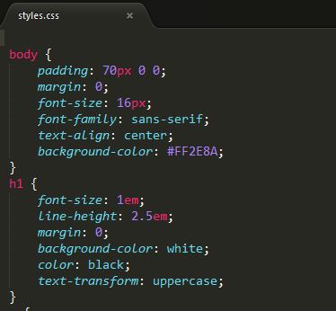
- CSS is used to define styles for your Tile, including the design, layout, and variations in the display for different devices and screen sizes.
- Link scripts and styles. It also describes the application contents.
- Follow steps at Uploading Tiles to run the module Tile
- pen nexpaq application
- Select your Developer’s board detected by your Bluetooth device
- Select module slot that popped up
- Run LEDRgB example!
ADC
In this resource you will experiment on how to send ADC values using a potentiometer. General ideas behind reading an analog input, sending ADC and Voltage value through hardware to a custom application will be shown
By following this example with nexpaq Developer Kit you will learn:
- How to develop a nexpaq firmware application
- How to create a simple module application
- How to communicate the hardware with the Tile
Throughout the documentation we will define upstream and downstream as follows:
- Upstream: Communication from Firmware to Tile (Module Interface)
- Downstream: Communication from Tile to Firmware
- 1 x Breadboard
- male – female connectors and jumper wires
- 1 x 10K ohm potentiometer
- 1 x nexpaq Dev_Module
- 1 x nexpaq Developer’s board
- 1 x MSP-EXP430G2 LaunchPad
- 1 x smartphone
- CCS IDE
- Any text editor (such as Sublime Text and Atom)
- nexpaq application

- Click on ADC to download the CCS code
- Flash the module with LEDrGB code using TI LaunchPad (Follow procedure listed at Flashing the MSP module under Getting Started)
- Main code is included at tmain.cpp file
- At np_api_loop() values on the potentiometer are saved into a variable called pot_value.
- As pot val is an ADC value is 10 bit length.
- For sending the value to the Tile np_api_upload function is used. This function has 3 parameters.
- 2800 corresponds to the command for sending data to the app.
- send_pot_value: the array composed by 2 elements and ADC is 10 bit. 2 element of sending array must be used to send ADC value, as each element on send_pot_value is 8 bit length.
- 2 corresponds to sending array length
KEEP IT IN MIND
If just upstream communication is used, t_my_app files at CCS project don’t need to be used. This files are used just for downstream communication.
- Once the MSP module is programmed, set up Potentiometer in a breadboard as shown in the image bellow
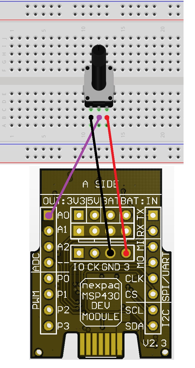
- After everything is connected you can plug the chip into the board, with the pins facing outwards. If they point inward, the Developers board won’t be able to connect to the MSP.
- Download nexpaq application
- Download ADC Tile
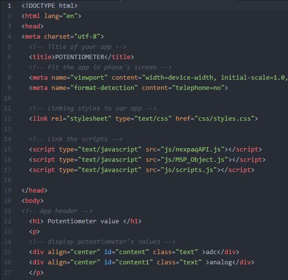
nexpaq custom module applications include four different files:
- Scripts (Java Script files)
- Styles (css files)
- Index (html file)
- img (images)
- Scripts files include Java Script files for Tile function, API and DevMod_Object. nexpaqAPI and DevMod_Object are library files. Module function is defined at scripts.js.
- First of all, MSP module must be set
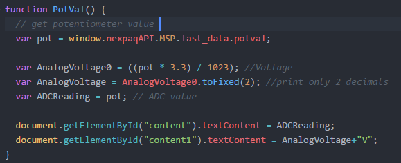
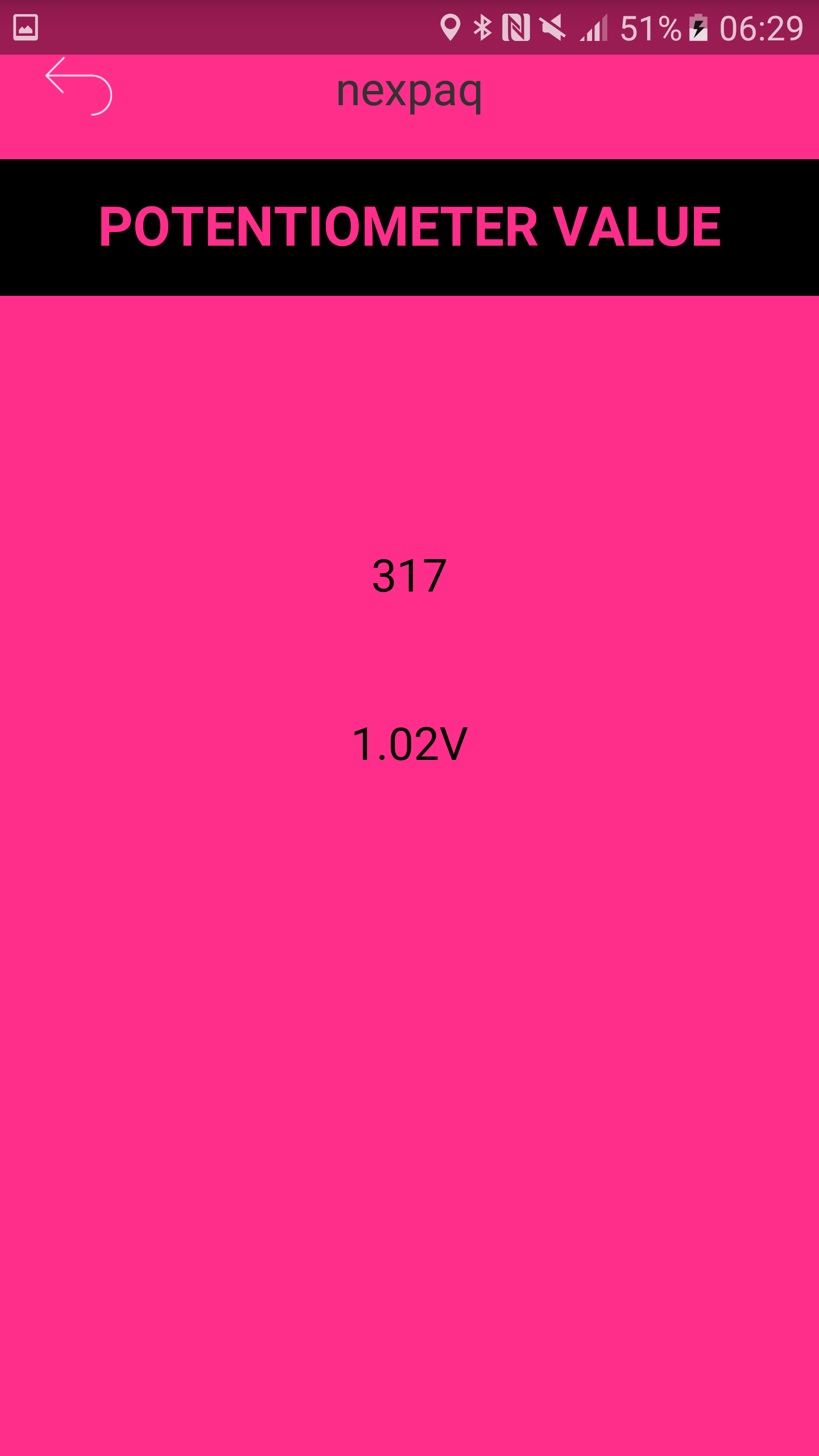
- New data is received after changing potentiometer’s value on the breadboard (spinning the knob) and PotVal function is executed.
- PotVal function has the necessary operations to display at the app ADC and Voltage values.
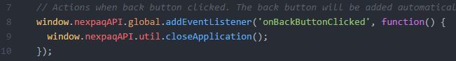
- Backbutton at Potentiometer app is used to close the application
- CSS is used to define styles for your Tile, including the design, layout and variations in display for different devices and screen sizes.
- Link scripts and styles. It also describes the application contents.
- Follow steps at Uploading Tiles to run the module Tile
- Open nexpaq application
- Select your Developer’s board detected by your Bluetooth device
- Select module slot that popped up
- Run ADC example!
I2C
In this resource you will experiment on how to use I2C communication by using a SHT20 Temperature & Humidity sensor.
By following this example with nexpaq Developer Kit you will learn:
- How to develop a nexpaq firmware application
- I2C communication
- How to create a simple module application
- How to communicate the hardware with the Tile
Throughout the documentation we will define upstream and downstream as follows:
- Upstream: Communication from Firmware to Tile (Module Interface)
- Downstream: Communication from Tile to Firmware
- 1 x Breadboard
- male – female connectors and jumper wires
- 1 x Temperature & Humidity sensor SHT20
- 1 x nexpaq Dev_Module
- 1 x nexpaq Developer’s board
- 1 x MSP-EXP430G2 LaunchPad
- 1 Android Phone
- CCS IDE
- Any text editor (such as Sublime Text and Atom)
- nexpaq application
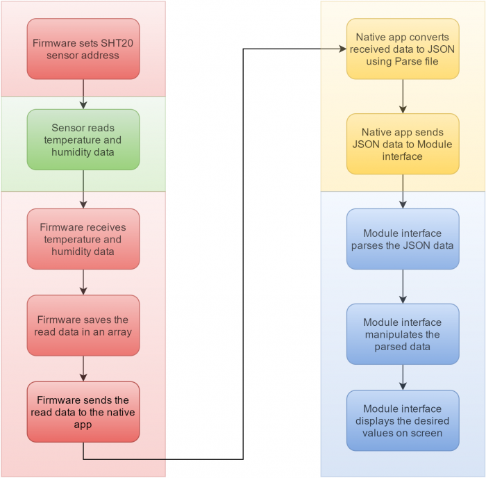
Flow diagram
- Click on SHT20 to download the CCS code
- Flash the module with LEDrGB code using TI LaunchPad (Follow procedure listed at Flashing the MSP module under Getting Started)
- Additional library is used for I2C(*) communication.
- Following commands from I2C library are used to communicate with SHT20 sensor:
- I2C.begin -> set slave’s(**) address. The address for SHT20 sensor is found at its datasheet
- I2C.I2C_Rx -> command to receive data from slave. Different address is used for reading temperature or hummidity.
- After getting temperature and hummudity values, an array (data_send) is built in order to send data to the Tile.
(*) This library uses specific pins on Dev_Module supporting I2C (P01 and P02). Another library simulating I2C can be used if using different pins (this is a software simulation on I2C communication protocol).
(**)Master/slave is a model of communication where one device or process has unidirectional control over one or more other devices
- Main code is included at tmain.cpp file
- At np_api_loop data from the sensor is stored in two different array, one for temperature and one for hummidity.
- After getting the correct values on both temperature and humidity, data is stored in a 4 bit length array (data_send).
- Once the Dev_Module is flashed, attach SHT20 sensor in a breadboard as shown in the image bellow
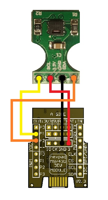
- After everything is connected you can plug the chip into the board, with the pins facing outwards. If they point inward, the Developers board won’t be able to connect to the MSP.
- Download SHT20 Tile
nexpaq custom module applications include four different files:
- Scripts (Java Script files)
- Styles (css files)
- Index (html file)
- img (images)
- Scripts files include Java Script files for Tile function, API and DevMod_Object. nexpaqAPI and DevMod_Object are library files. Module function is defined at scripts.js.
- First of all, Dev_Module must be set
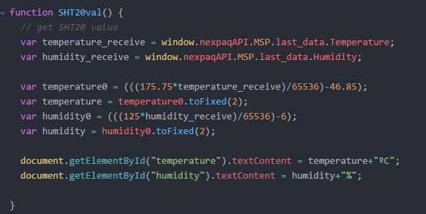
- A function called SHT20val is used to get Temperature and Humidity values . “onDataReceived” is a function which updates this values whenever are changed.
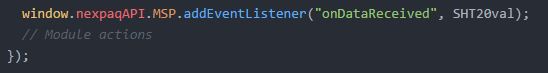
- In order to get correct values on temperature and humidity some operations are done at SHT20val function
- Backbutton at SHT20 tile is used to close the application
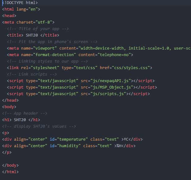
- CSS is used to define styles for your Tile. including the design, layout and variations in display for different devices and screen sizes.
- Link scripts and styles. It also describes the application contents.
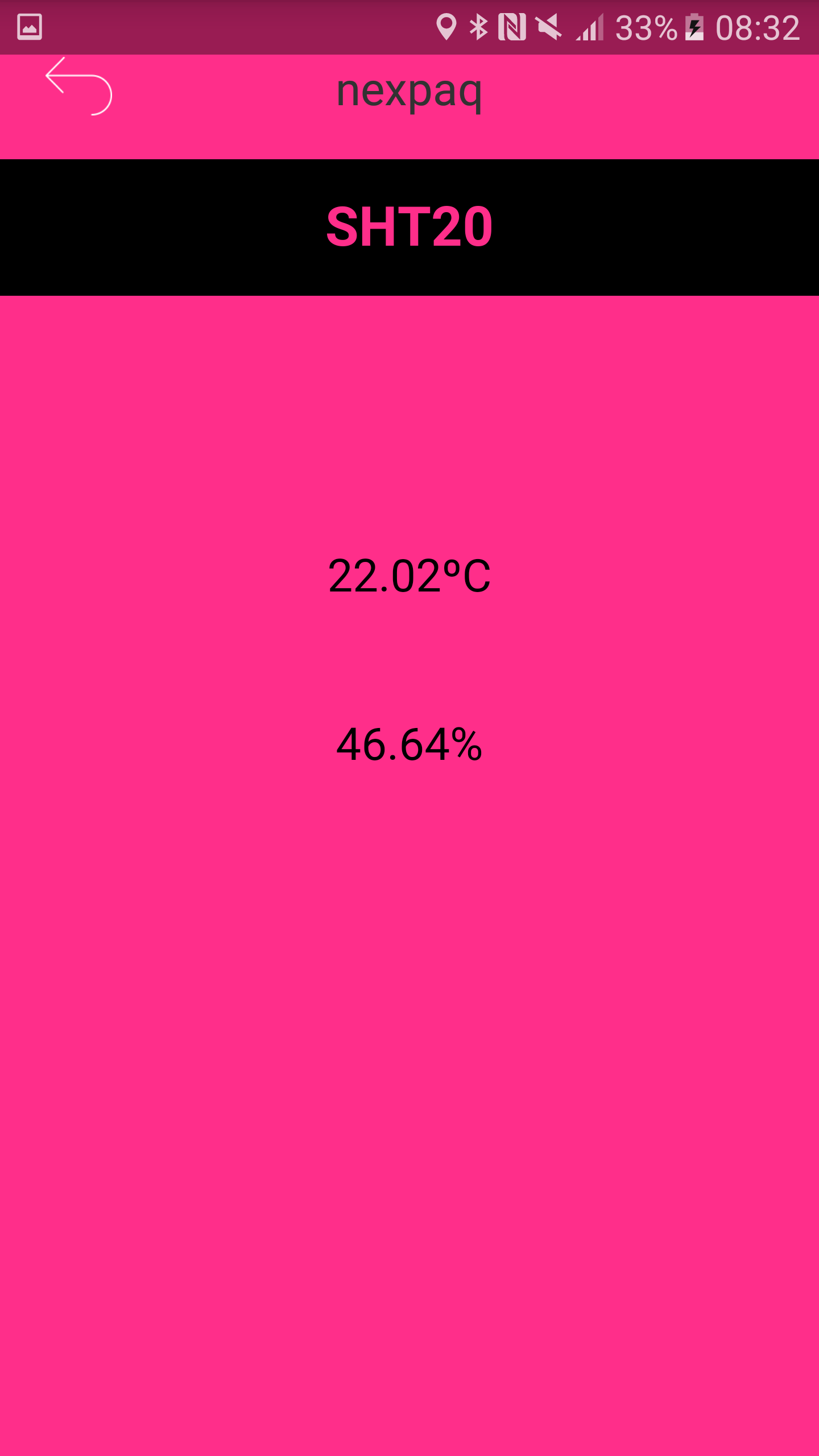
- Follow steps at Uploading Tiles to run the module Tile
- Open nexpaq application
- Select your Developer’s board detected by your Bluetooth device
- Select module slot that popped up
- Run SHT20 example!
UART – MSP <> ARDUINO
In this resource you will experiment on how to connect Arduino and MSP module via UART software library
By following this example with nexpaq Developer Kit you will learn:
- How to develop a nexpaq firmware application
- How to create a simple module application
- How to communicate MSP module to Arduino via UART software library.
Throughout the documentation we will define upstream and downstream as follows:
- Upstream: Communication from Firmware to Tile (Module Interface)
- Downstream: Communication from Tile to Firmware
- 1 x Breadboard
- male – female connectors and jumper wires
- 2 x LED
- 2 x 1k ohm ¼ W 1% resistor
- 1 x nexpaq Dev_Module
- 1 x nexpaq Developer’s board
- 1 x MSP-EXP430G2 LaunchPad
- 1 Android Phone
- 1 x Arduino UNO
- Arduino IDE
- CCS IDE
- Any text editor (such as Sublime Text and Atom)
- nexpaq application
- Click on UART_CCS to download the CCS code
- Click on UART.ino to download the Arduino code
- Flash the module with UART_CCS code using TI LaunchPad (Follow procedure listed at Flashing the MSP module under Getting Started)
- Flash Arduino with UART.ino code
- This is the library used for comunicating Dev_Module to Arduino. It is a software library on UART serial comunication
- It must include queue files
- Three functions are used:
1. Serial comunication settings
- serial.begin(): This function sets parameters requiered for synchronizing both devices.
- speed: Sets the data rate in bits per second (baud) for serial data transmission. In this example is 115200
- config: Number of bits transmitted, parity of this bits and number of stop bits. According to Arduino settings; 8 bit are transmitted, parity is None and 1 is the number of stop bits. 8N1 is the config parameter settings.
- By using this library TX and RX PINS are set as default:
- TX PIN corrsponds to 8
- RX PIN corrsponds to 9
2. DEV_MOD <> ARDUINO
- serial.write(): Transmits information from Dev_Module to Arduino. In this case fields requiered are buffering and length.
- buf: buffer array to send information from Dev_Module to Arduino. For this example the information to the Arduino comes from the Tile. After pushing ON/OFF button from the Tile, Dev_Module gets the information and then is transmitted to Arduino. Arduino has an LED attached that is controlled from the Tile.
- len: length of the buffer array
3. ARDUINO <> MSP
- serial.read() : get data from Arduino to Dev_Module.
- Main code is included at tmain.cpp file
- A function from the MDK – MDK_REGISTER_CMD – is used to light the LED attached to Arduinio from nexpaq phone application . It requires two items:
- command: From 2700 to 27ff
- function: function’s name
- For this example one command from the function is used, ON_OFF_button.
- At np_api_setup, PIN 0 is set as an output in order to make the LED blink once comunicating with Arduino
- Serial settigs are also made at np_api_setup loop. Speed (115200 baud) must be the same as serial speed in Arduino firmware settings.
- At np_api_loop twoo different actions are performed:
- After getting button status information from the Tile, data is send to Arduino to turn ON/OFF an LED attached to Arduino
- Once Dev_Module and Arduino are comunicating (Dev_Module reads an integer corresponding to 5) and LED attached to Dev_Module starts to blink
- A function from the MDK – MDK_REGISTER_CMD – is used to light the LED attached to Arduinio from nexpaq phone application . It requires two items:
- t_my_app file is used to specify downstream communication and module’s function. pData is an array sent from Tile. len parameter gets the lengh of the array.
- Gets button status on ON/OFF button from the Tile.
NOTE: On_Off_button
!IMPORTANT : MDK_REGISTER_CMD function’s name must be the same at tmain.cpp, t_my_app.c and t_my_app.h.
- A UART library is also included at Arduino’s code called SoftwareSerial.
- Pins for RX and TX are set at 10 and 11
- Data rate for serial port is set as 11500, the same data rate on Dev_Module code.
- After the serial comunication is avaliable an integer value is read by Dev_Module. After Dev_Module serial read, and the LED attached to Dev_Module starts to blink. This ensures the comunication from Arduino to Dev_Module.
- On the other side, after Dev_Module sends an integer corresponding to 1, the LED attached to Arduino turns on.
- Once the Dev_Module is flashed, set up the components in a breadboard as shown in the image bellow
                                DEV_MOD <> ARDUINO
                                  P08 <> P10
                                  P09 <> P11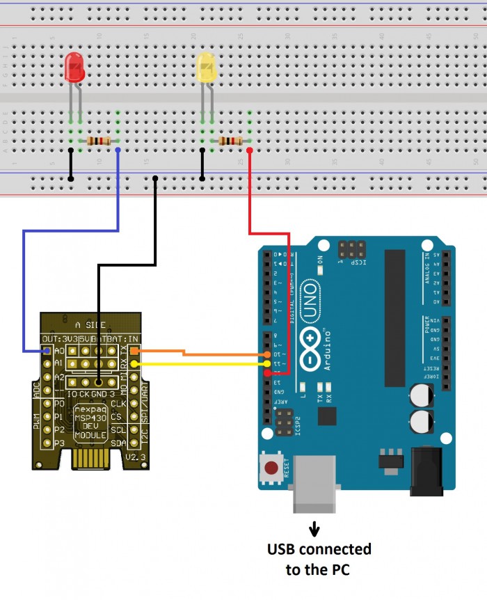
!IMPORTANT : Connect Arduino and Developers board to the same PC
After everything is connected you can plug the chip into the board, with the pins facing outwards. If they point inward, the Developers board won’t be able to connect to the MSP.
- Download UART_TILE
nexpaq custom module applications include four different files:
- Scripts (Java Script files)
- Styles (css files)
- Index (html file)
- img (images)
- Scrips files include Java Script files for module function, API and Dev_Module object. nexpaqAPI and DEV_MOD are library files. Module function is defined at scripts.js.
- First of all, MSP must be set
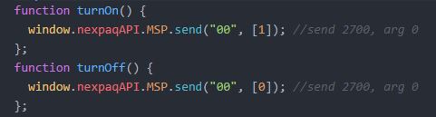
- For this example two funcions are performed when clicking ON or OFF buttons
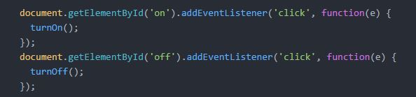
- Each function sends a different parameter to the native app. To send data a function from nexpaqAPI is used. It must include two parameters: address and pData. Address consist of two numbers, from 00 to FF. In order to turn ON or OFF the LED attached to Arduino, address 00 is used with two different arguments (pData).
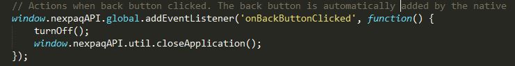
- Backbutton at this tile is used to exit
- CSS is used to define styles for your tile, including the design, layout and variations in display for different devices and screen sizes.
- Link scripts and styles. It also describes tile contents.
- Follow steps at Uploading Tiles to run the module Tile
- Open nexpaq application
- Select your Developer’s board detected by your Bluetooth device
- Select module slot that popped up
- Run this example!
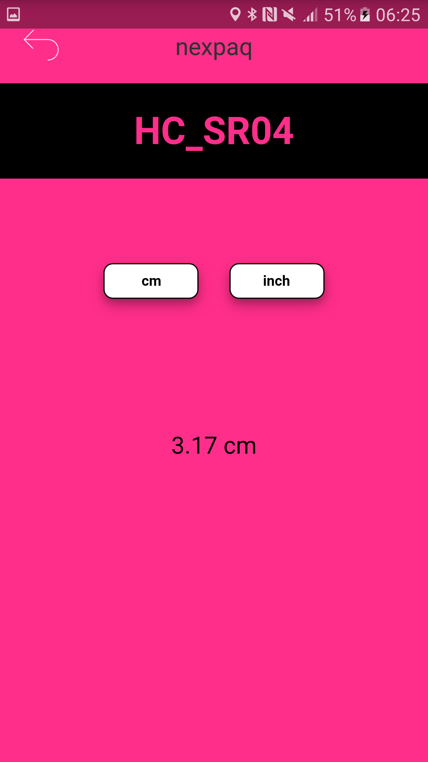
HC-SR04 – Distance Measurement
In this resource you will experiment on how to use HC-SR04 ultrasonic sensor by getting a distance measurement in both inches and centimeters
HC-SR04 ultrasonic sensor uses sonar to determine distance to an object.
By following this example with nexpaq Developer Kit you will learn:
- How to develop a nexpaq firmware application
- How to create a simple module application
- How to communicate the hardware with the Tile using Ultrasonic sensor library
Throughout the documentation we will define upstream and downstream as follows:
- Upstream: Communication from Firmware to Tile (Module Interface)
- Downstream: Communication from Tile to Firmware
- 1 x Breadboard
- male – female connectors and jumper wires
- 1 x Ultrasonic sensor HC-SR04
- 1 x nexpaq MSP module
- 1 x nexpaq Developer’s board
- 1 x MSP-EXP430G2 LaunchPad
- 1 Android Phone
- CCS IDE
- Any text editor (such as Sublime Text and Atom)
- nexpaq application
- Download HC sensor for CCS code
- Flash the module with LEDrGB code using TI LaunchPad (Follow procedure listed at Flashing the MSP module under Getting Started)
- Main code is included at tmain.cpp file
- A library is used to get the mesurements from the sensor. The aim is to control the trigger (Trig) and the response (Echo) pins on the sensor. Trigger is the pin for comunicating to the ultrasonic transmitter and Echo is responsible for receiving the ultrasonic wave back.
- For initializing the sensor is required to use the command US_s.Initialitzation()
- US_s.Trigger() generates the ultrasonic wave.
- After receiving the Echo wave, it is saved to ClockTime variable.ClockTime variable sends measurement data to the Tile after the measurement is finished (finish_measurement variable).
KEEP IT IN MIND
If just upstream communication is used, t_my_app files at CCS project don’t need to be used. These files are used just for downstream communication.
- Once the Dev_Module is programmed, set up the HC-SR04 as shown in the image bellow
                                 DEV_MOD  - HC-SR04
                                   P0 - Trig
                                   P8 - Echo
                                  GND - GND
                                  Vcc - 5V (Dev. Board)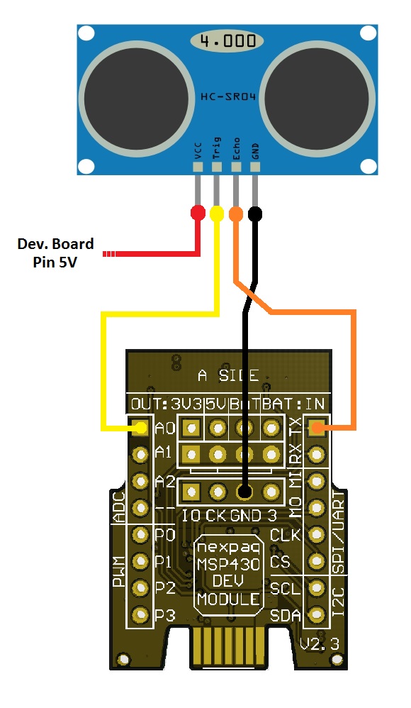
- After everything is connected you can plug the chip into the board, with the pins facing outwards. If they point inward, the Developers board won’t be able to connect to the MSP.
- Download HC Tile
nexpaq custom module applications include four different files:
- Scripts (Java Script files)
- Styles (css files)
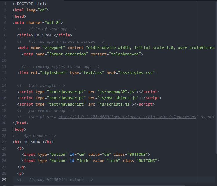
- Index (html file)
- img (images)
- Scripts files include Java Script files for module function, API and Dev_Module. nexpaqAPI and DEV_MOD are library files. Module function is defined at scripts.js.
- First of all, MSP must be set
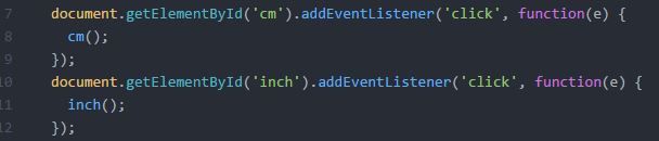
- For this sensor both inches and centimiters can be selected. After clicking a button on phone’s Tile to select either centimeters or inches, corresponding funcitons are executed.
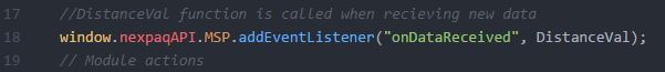
- Another function is used to calculate and display the Distance value, depending on the measurement type selected. “onDataReceived” is a function which updates the distance value whenever it changes.
- Backbutton at Potentiometer app is used to close the application
- CSS is used to define styles for your Tile, including the design, layout and variations in display for different devices and screen sizes.
- Link scripts and styles. It also describes the application contents.
Servo + Potentiometer Challenge
This challenge connects upstream and downstream communication in one single application.
By following this example with nexpaq Developer Kit you will learn:
- How to develop a nexpaq firmware application
- How to create a simple module application
- How to communicate the hardware and the Tile
Throughout the documentation we will define upstream and downstream as follows:
- Upstream: Communication from Firmware to Tile (Module Interface)
- Downstream: Communication from Tile to Firmware
- 1 x Breadboard
- 6 x male – female connectors and jumper wires
- 1 x nexpaq Dev_Module
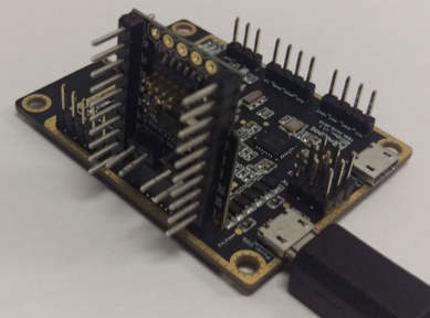
- 1 x nexpaq Developer’s board
- 1 x MSP-EXP430G2 LaunchPad
- 1 x Android Phone
- 1 x Servo SG90
- 1x 10K Ohm Potentiometer
- CCS IDE
- Any text editor (such as Sublime Text and Atom)
- nexpaq application
- Download Servo+Potentiometer for CCS code.
- Flash the module with LEDrGB code using TI LaunchPad (Follow procedure listed at Flashing the MSP module under Getting Started)
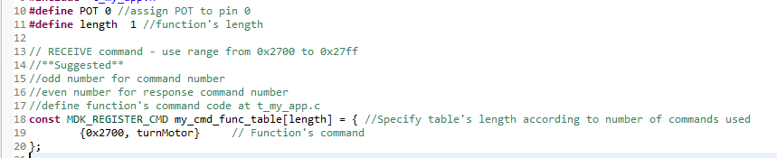
- The first two lines here specify the pin to which the MSP will be reading analog data from, Pin A0 in this case. Next, we define the length of the array containing functions, we only have 1, turnMotor.
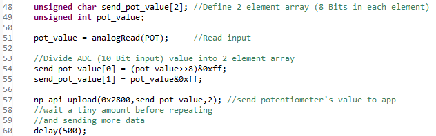
-Lines 48-60 are all inside of the np_api_loop loop which runs continuously while the chip is not in sleep mode. First we create a 2 byte array, send_pot_value. Next, we use pot_value to store recent data. The data is then placed in the array and uploaded to the phone using “2800” tag.
IMPORTANT : When using downstream communication, function’s must have the same name at tmain.cpp, t_my_app.c and t_my_app.h.
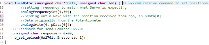
- t_my_app function takes in an array, pData, and len, the length of pData.
- AnalogFrequencySet sets the correct frequency to output, in this case, the motor requires a pulse every 20 milliseconds (or 50 Hz). There is two parameter needed to set:
- The first parameter takes in a PIN (PIN 4 is used in this example)
- The second parameter takes in a frequency in HZ (50 Hz for this example).
- AnalogWrite takes in the same first parameter for PIN, but the second is different. It is the percent of the pulse that is the duty cycle.
- First, connect the Potentiometer to the MSP module
- Once that’s all connected, the motor can be attached
- Brown cable is ground, red cable is 5V, orange cable can plug into A0 on the MSP module.
- The 5V and Ground should be attached to the developer board itself.
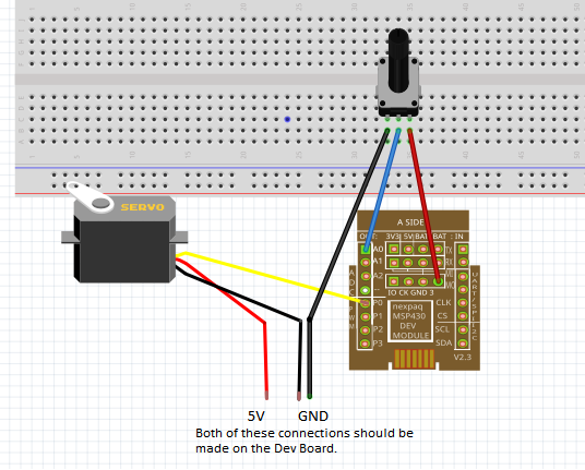
- After everything is connected you can plug the chip into the board, with the pins facing outwards. If they point inward, the Developers board won’t be able to connect to the MSP.
- Download Servo+Potentiometer Tile
nexpaq custom module applications include four different files:
- Scripts (Java Script files)
- Styles (css files)
- Index (html file)
- img (images)
- Scrips files include Java Script files for module function, API and Dev_Module. nexpaqAPI and DEV_MOD are library files. Module function is defined at scripts.js.
- First of all, Dev_Module must be set
- The scripts file defines what the buttons do and what functions to call based on user input, or none at all.
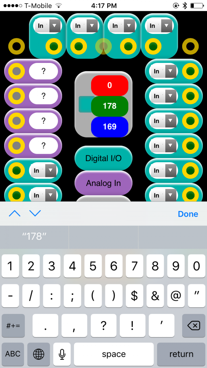
- In this tutorial, the user input is analog, converted to digital, displayed in the tile, and then sent back down for analog use.
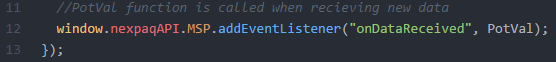
- This bit of code from the scripts file calls the function PotVal when new data is received, we define it below.
- It, takes the raw ADC value and converts it to Volts, displays that value in the app, and then sends data back down to turn the motor.
- The position is sent to the turnMotor function we discussed earlier.
- CSS is used to define styles for your Tile, including the design, layout and variations in display for different devices and screen sizes.
- Link scripts and styles. It also describes the application contents.
LCD
By following this example with nexpaq Developer Kit you will learn:
- How to develop a nexpaq firmware application
- How to create a simple module application
- How to communicate the hardware and the Tile
Throughout the documentation we will define upstream and downstream as follows:
- Upstream: Communication from Firmware to Tile (Module Interface)
- Downstream: Communication from Tile to Firmware
- 1 x Breadboard
- male – female connectors and jumper wires
- 2 x 10k ohm ¼ W 1% resistor
- 1 x LCD I2C 16X02
- 1 x nexpaq Dev_Module
- 1 x nexpaq Developer’s board
- 1 x MSP-EXP430G2 LaunchPad
- 1 smartphone
- CCS IDE
- Any text editor (such as Sublime Text and Atom)
- nexpaq application
- Download LCD for CCS code.
- Flash the module with LEDrGB code using TI LaunchPad (Follow procedure listed at Flashing the MSP module under Getting Started)
- Once the MSP module is flashed, set up the LCD in a breadboard as shown in the image bellow
After everything is connected you can plug the chip into the board, with the pins facing outwards. If they point inward, the Developers board won’t be able to connect to the MSP.
- Download nexpaq application
- Download LCD Tile
nexpaq custom module applications include four different files:
- img (images)
- Index (html file)
- Styles (css files)
- Scripts (Java Script files)
-
Install Tile to nexpaq application
- Follow steps at Uploading Tiles to run the module Tile
- Open nexpaq application
- Select your Developer’s board detected by your Bluetooth device
- Select module slot that popped up
MAX Resources
LESSON 1 – Installation and Operation
- To get started with the nexpaq platform
- In this lesson you will learn:
- Where to find the nexpaq app
- How to download code into the app
- How to install and use the default developer’s tile
- Install any text editor for code, markup and styles (such as Brackets, Sublime Text, Atom)
- Download the nexpaq application for your device
- Install Terminals
- For iPhone: Have phone connected to iTunes
- For Android on Mac: install Android File Transfer
- For Windows: install mbed driver Windows-serial-configuration
- If on iOS, after the nexpaq installation go to Settings > General > Device Management, select Nexpack Ltd and “trust”.
- If on Android go to Settings > Security > Device Administration > Unknown sources and allow installation of apps from unknown sources
Setting up the nexpaq application
- Power Mini Developer Board
- Open up nexpaq application and turn on the Bluetooth on the phone
- Login in / Register on the nexpaq application
- After logged in, select the developer board by clicking on it (a right click appears when the board is selected) and Click on Connect
- If the connection between the Mini Dev Board and the phone application is successful a message is displayed at the top of the application.
- Check if there is any notification by clicking on Notifications tab
- Plug the Developer Module to the Developer’s board slot. Its very important that the PINS on the Developers Module are facing out
- Click on the Developer’s tile after it shows up
- Adjust the R/G/B values to change the LED’s color
- Wire potentiometer to AIN_0
- Connect pot between 3V3 and GND
- Connect wiper to AIN_0
- Turn knob and see voltage change
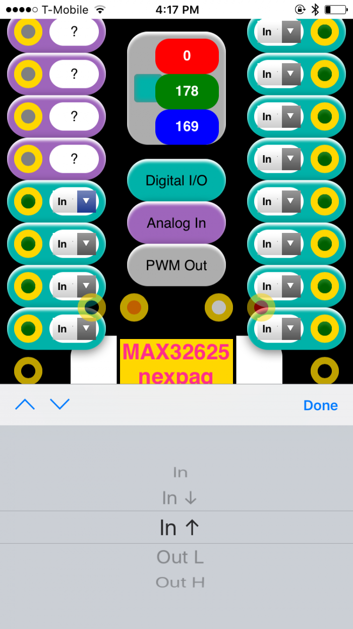
- Wire P1_6 to P1_7
- Change P1_7 to Out L then Out H
- See the status change on P1_6
LESSON 2 – Installation and Flashing
- Objectives:
- Get started with the nexpaq platform by lighting an LED via a push button using the MAX32625 module and the nexpaq application
- In this lesson you will learn:
- Where to find developer resources
- Where to find the nexpaq app
- How to download code into the app
- How to flash firmware onto the module
Download Files
- Tile for LED_Demo_Tile
- Firmware for LED_DEMO_MAX32625.bin
- iPhone
- Plug the iPhone into the computer via USB
- Extract files from LED_Demo_Tile.zip
- Use iTunes to transfer module and tile directories to the iPhone
- For detailed instructions with images follow Uploading Tiles for iPhone
- Android
- Extract files from LED_Demo_Tile.zip
- Connect phone to computer with USB cable and enable MTP access
- Copy module and tile folders to the nexpaq folder (use Android File Transfer on Mac)
- For detailed instructions with images follow Uploading Tiles for Android
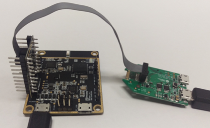
- Connect an HDK to the module
- HDK ribbon cable connects to the module
- Plug the Developer Module to the Developer’s board slot. Its very important that the PINS on the Developers Module are facing out
- HDK connects to a computer
- Mini Dev Board connects to a computer.
- After connecting all devices, the MAX module is detected on the computer as a Flash Device under MBED name.
- The MAX is flashed by drag and drop files onto the MBED drive
- Using a bread board, wire button up the module as shown
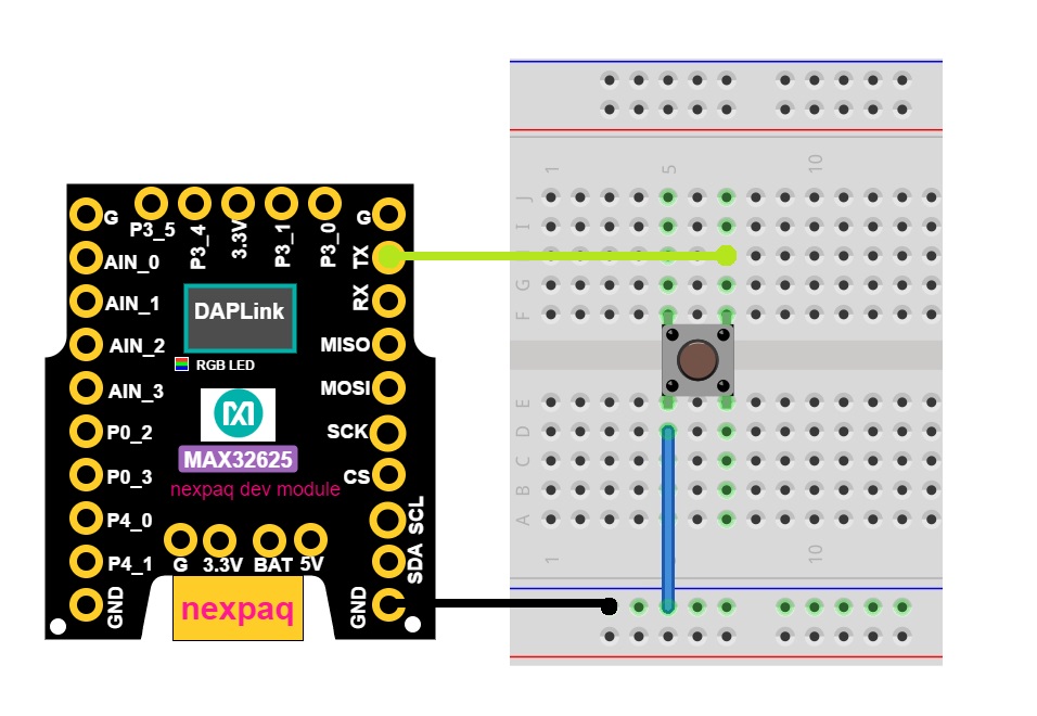
- Ensure the mini dev board is powered
- Plug in the module with it’s pins facing away from mini dev board
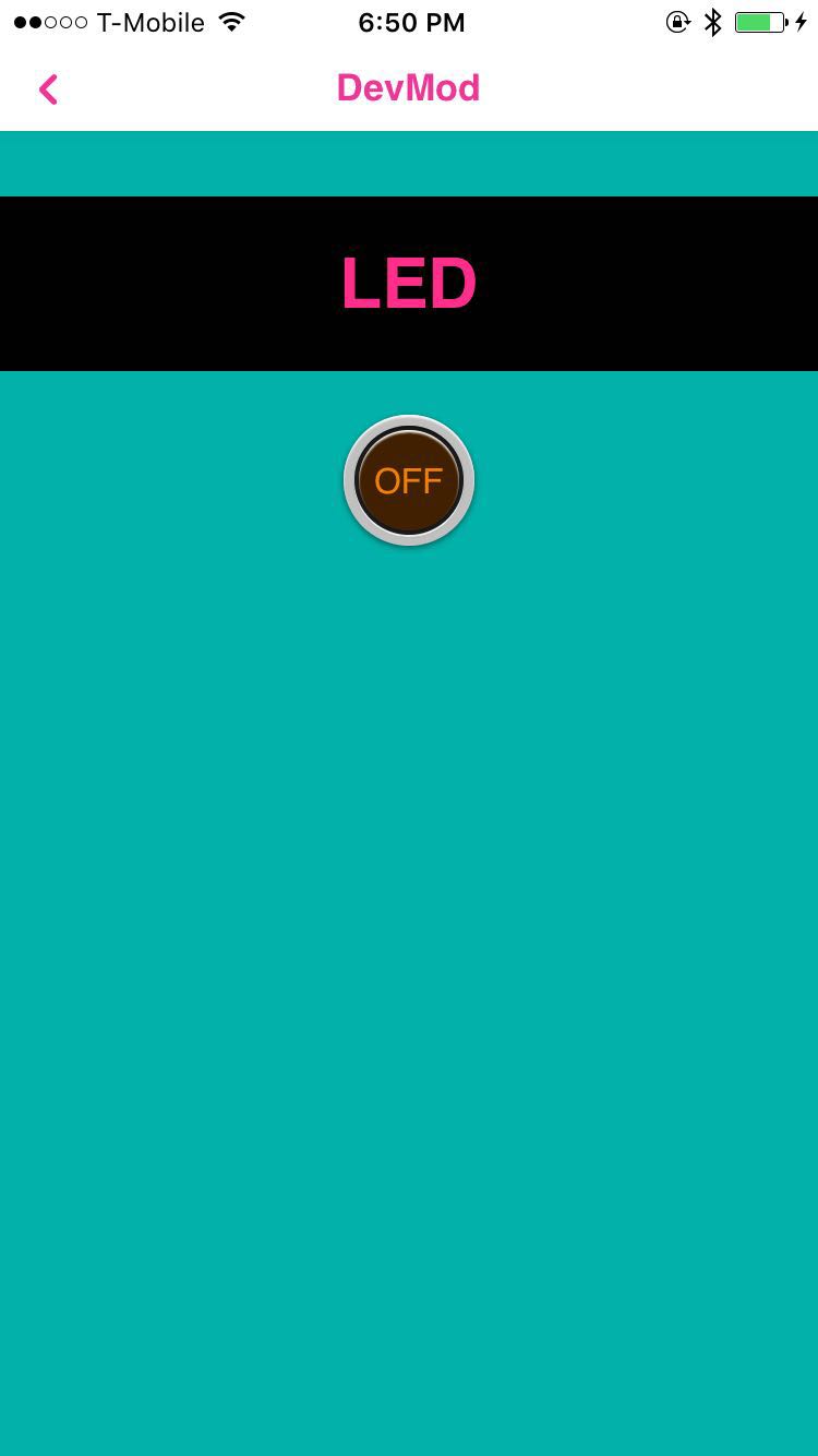
- Launch the nexpaq app
- Search for and connect to the mini dev board
- Click on DevMod tile to run
- Press the push button on the bread board or the on screen button to toggle the LED on and off.
LESSON 3 – Tile Development
- Objectives:
- Add some code to the tile that the LED can display any color
In this lesson you will:
- Learn how to customize a tile
- Learn how to edit objects in HTML
- Learn how to customize appearance in CCS
- Learn how to program features in JavaScript
- The firmware and tile for starting up with this lesson are the same files as previous lesson (lesson 2)
Lesson 2 Files
- Tile for LED_Demo_Tile
- Firmware for LED_DEMO_MAX32625.bin
HTML
- Open index.html
- Insert the following code immediately before
</body>
CSS
- Open css directory and styles.css file
- Insert the following code at the end of the file
JS
- Open js directory and scripts.js file
- Replace the following code at ‘updateLED()’ function
- Load updated tile code onto phone as was done in Lesson 2.
- Make sure hardware is still connected as described in Lesson 2.
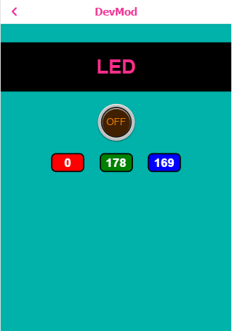
- Run the tile in the app
- Notice the new input type to type any RGB color
- Change the color of the LED and background at the same time.
LESSON 4 – Firmware Development
- Objectives:
- Use a MAX44000 ambient light sensor with an integrated infrared proximity sensor to toggle the LED
- In this lesson you will learn to program the module firmware
- Learn how to import projects in mbed
- Learn how to compile programs in mbed
- Learn how to flash an image frim mbed
- Install to the phone the files for the tile corresponding to the end of Lesson 3 (if the previous lesson has not been followd up)
- Lesson 3 Files
- Tile for LED_prox_Demo Tile
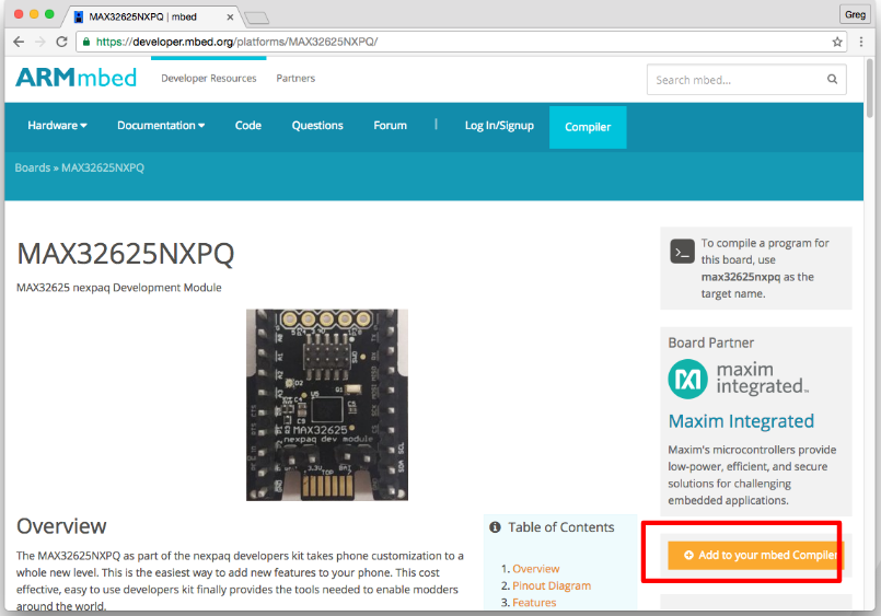
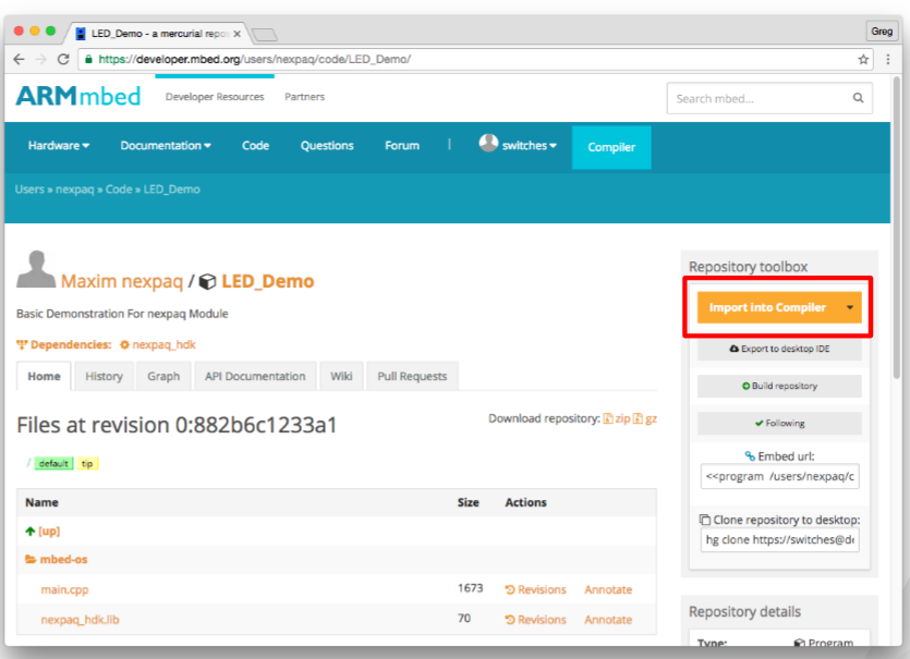
- Go to the max32625 nexpaq platform and Log on
- Click “Add to your mbed compiler’
- Go to LED Example Project Page.
- Click on Import Compiler
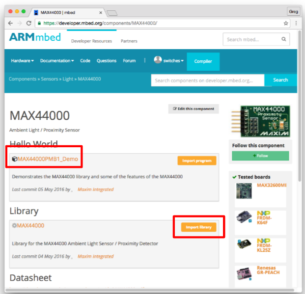
- Go to the MAX44000 Component page
- Click ‘Import Library’
- Click MAX44000PMB1_Demo to see example code
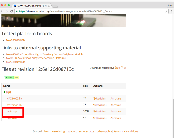
- Go to the MAX44000PMB1_Demo Project Page
- Scroll to the bottom of the page
- Click “main.cpp” to see example code
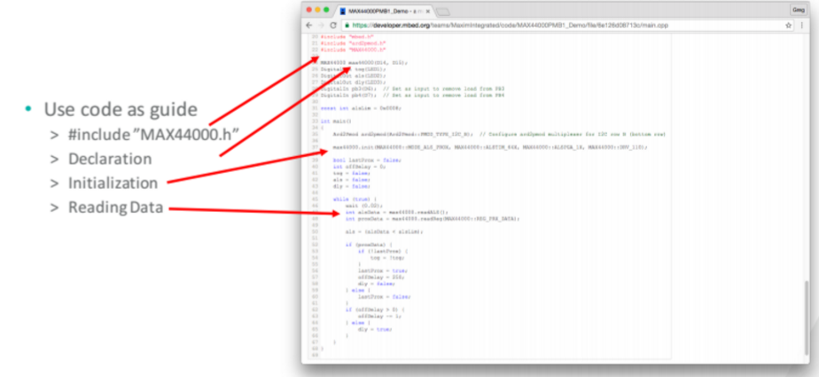
- Add this line to the list of #includes
include "MAX44000.h" - Add this line right after #includes
MAX44000 max44000(P1_6, P1_7); PwmOut ledR(P2_4); PwmOut ledG(P2_5); PwmOut ledB(P2_6); - Add this line to the list of #defines
#define PROX_THRESHOLD 50 - Declare the following variables
int lastPrx = 0; unsigned char prxPress = 0x02; - Add the following code inside Funcions
ledR = 1.0f - (pData[0] / 255.0f); ledG = 1.0f - (pData[1] / 255.0f); ledB = 1.0f - (pData[2] / 255.0f); - Add the following code inside app_setup()
max44000.init(MAX44000::MODE_ALS_PROX, MAX44000::ALSTIM_64X, MAX44000::ALSPGA_1X, MAX44000::DRV_110); ledR = 1.0f; ledG = 1.0f; ledB = 1.0f; - Add the following code inside app_loop()
 int proxData = max44000.readReg(MAX44000::
 REG_PRX_DATA);
 if (proxData > PROX_THRESHOLD) {
    if (!lastPrx) {
    np_api_upload(0x2800, &prxPress, 1);
    }
 lastPrx = 1;
 } else {
 lastPrx = 0;
}
- Connect the HDK to module as shown bellow
- HDK ribbon cable to module
- Module plugged into Mini Dev Board
- HDK connected to computer
- Mini Dev Board connected to computer
- Drag and drop file onto mbed drive
- Once the MAX32625 module is flashed, set up as shown in the image bellow
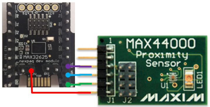
- Change the color of the LED
- Wave hand over proximity sensor
LESSON 5 – Customizing the API
- Objectives:
- Capture sensor data from proximity sensor
- Add code to control.json, parse.json and manifest.json
- In this lesson you will learn how to customize the module API
- Learn how to use the manifest file
- Learn how to use the control file
- Learn how to use the parse file
- Use the tile code from completed lesson 4 or download from this link LED_Prox_Demo
- Use firmware code from completed lesson 4 or dowload from this link LED_Prox_Demo.bin
- Specifies attributes for a module
Attributes
- “fun”: defines function name
- “data”: Specifies which elements
of data array to use - format: Formats data from array
Attributes
- “name”: Provides name for element
in javascript - “cmd”:
- Specifies number used for
this command - All command numbers begin
with 39 (0x27) - Odd numbers reserved for
acknowledge
- Specifies number used for
- Add the following code to html before the closing body tag.
- Add styles for the new elements:
- Add updateProx function and edit dataHandler:
- Use the firmware source form Lesson 4 or go to this link:
- Add this line to the list of #defines
#define ALS_INTERVAL 10 // about once per second - Add the following code for declaring Global variables
void my_function_CMD_2700(unsigned char *pData, unsigned char len); void my_function_CMD_2702(unsigned char *pData, unsigned char len); const MDK_REGISTER_CMD my_cmd_func_table[FUNCTION_TABLE_NUM] = {{0x2700, my_function_CMD_2700}, // Command -> function {0x2702, my_function_CMD_2702}, // Command -> function}; - Declare the following variables
int alsCnt = 0; int prxThrsh = PROX_THRESHOLD ; - Add the following Function
void my_function_CMD_2702(unsigned char *pData, unsigned char len) { unsigned char response = 0x00; prxThrsh = pData[0] ; np_api_upload(0x2703, &response, 1); } - Add the following code
 void sendALS()
 {
 unsigned char pData[3];
 max44000.writeReg(MAX44000::REG_MAIN_CONFIG, 0x20);
 pData[0] = 10;
 pData[1] = max44000.readReg(MAX44000::REG_ALS_DATA_HIGH);
 pData[2] = max44000.readReg(MAX44000::REG_ALS_DATA_LOW);
 np_api_upload(0x2800, pData, 3);
 max44000.writeReg(MAX44000::REG_MAIN_CONFIG, 0x30);
 }
- Add the following code inside app_loop()
int proxData = max44000.readReg(MAX44000::REG_PRX_DATA);
if (proxData > prxThrsh) {
if (!lastPrx) {
np_api_upload(0x2800, &prxPress, 1);
}
lastPrx = 1;
} else {
lastPrx = 0;
}
if (!button && lastBtn) {
np_api_upload(0x2800, &btnPress, 1);
}
lastBtn = button;
alsCnt += 1;
if (alsCnt > ALS_INTERVAL) {
sendALS();
alsCnt = 0;
}
- Launch app and reconnect to the mini
dev board - Run the tile in the app
- Change the proximity threshold
- Wave hand over proximity sensor
- After making all the corresponding changes at the tile and the firmware the codes should be corresponding to the flowing files:
- Tile for ALS_Prox_Demo
- Firmware (bin file) ALS_Prox_Demo
- Page for ALS_Prox_Demo
Reference
Downloads
Hardware
- Download PDF for Housing dimensions
- Download bare minimum PCB components for MSP430
- Download bare minimum PCB components for MAX32625
MSP Examples
LED RGB
- Click on LEDrGB to download the CCS code
- Download LEDrGB Tile
ADC
I2C
UART
- Click on UART_CCS to download the CCS code
HC
Servo
- Download Servo+Potentiometer for CCS code.
- Download Servo+Potentiometer Tile
LCD
MAX tutorials
Lesson 1
Lesson 2
- Download LED_Demo.bin
- Download LED_Demo Tile
Lesson 3
- Download LED_Demo.bin
- Download LED_Prox_Demo Tile
Lesson 4
- Download LED_Demo.bin
- Download LED_Prox_Demo Tile
Dev Board update (v2016-02-01) or below
Follow steps behind in order to get ready the board for the new version!
Examples in this version requires to update developer’s board Firmware. BLE and MSP on board must be updated.
- Hardware needed: nexpaq Developer’s board, TI LaunchPad
- Software: FET- Pro 430
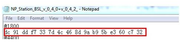
- Firmware File: NP_Station_BSL_v_0_4_0+v_0_4_2_.txt
Open NP_Station_BSL_v_0_4_0+v_0_4_2_.txt and change the first line to the UUID given. (Request for UUID writing to support@nexpaq.com)
Connect Developer’s board to the LaunchPad as the following image
                        DEV. BOARD  - LAUNCHPAD
                                RST - RST
                                TEST - TEST
                                GND - GND
                                3V3 - VCC
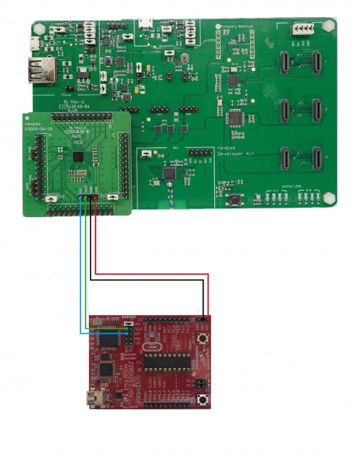
Connect LaunchPad to Computer through its USB cable
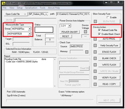
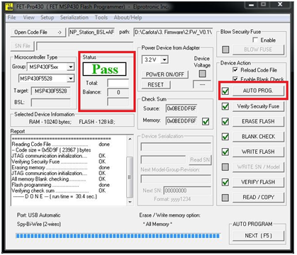
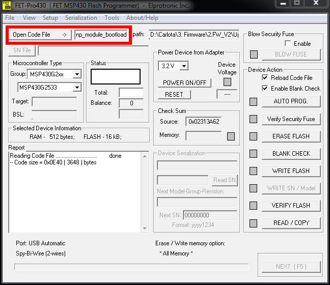
Open FET- Pro 430 and choose Microcontroller type as the following image. Also, tick on Device action.
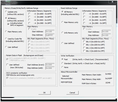
Click on Setup → Memory Options and set up the following options:
Click on AUTO PROG. and wait until the bootloader is uploaded. A Pass message will be displayed when the bootloader is uploaded.
- Hardware needed: nexpaq Developer’s board, CC2540 USB Dongle
- Software: BLE Device Monitor
- File Image: V_0_2_6_B.bin
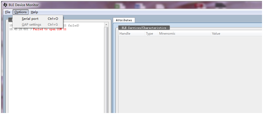
- Plug in a PC CC2540 USB Dongle and open the BLE Device Monitor
- Select the Options → Serial port
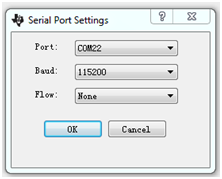
Set Serial Port settings according to the following image and Click OK
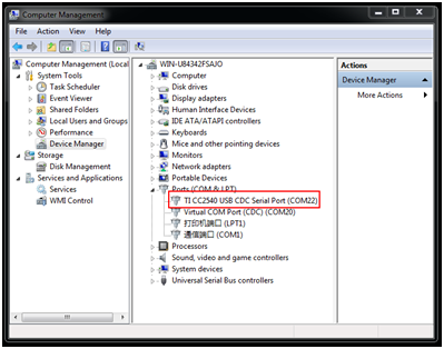
- Serial Port might be changed, the information about the corresponding serial port is found in Computer Management – Device Manager
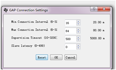
Select the Options → GAP Settings and set the Connection
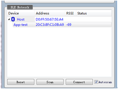
Power Developer’s board and click Scan. After Dev board is found, (in the image bellow is App-test) click Connect.
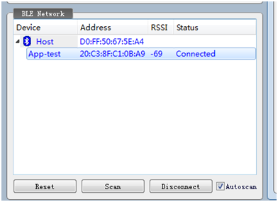
When connection is successful, Status will change from nothing to Connected
Select the File → Program (OAD) and will see the version of the Target Image (User ID code at the current Target image corresponds to A:A:A:A)
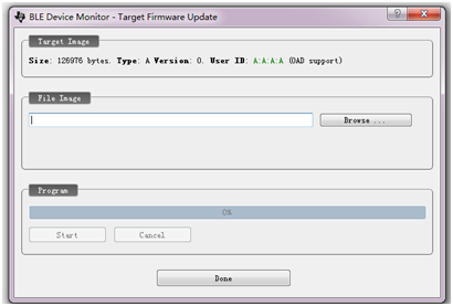
- Click Browse button and select new file Image (V_0_2_6_B.bin). User ID of this file is B:B:B:B.
- Click Start button and OAD will be updated.
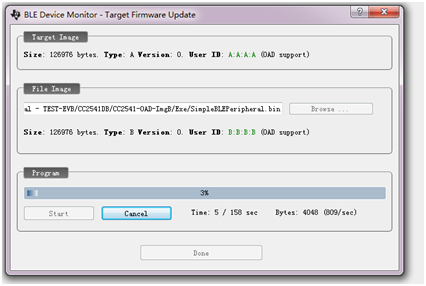
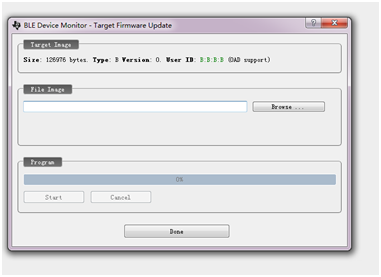
- When the file has been updated successful, this window will disappear and disconnect from Dev Board.
- Press the button on Developers board for 10s to restart it. After restarting first LED next to the button and second status LED on board should be both blues.
To double check that the upgrade is successful, connect again with the device and select File → Program (OAD), the User ID should have changed from A:A:A:A to B:B:B:B.
Upload bootloader to MSP module
If main memory is being erased when flashing MSP module, follow this document to upload it again
- Hardware needed: nexpaq MSP module, TI LaunchPad
- Software: FET- Pro 430
- Firmware File: np_module_bootloader_v_1_0_0.txt
Connect both devices, as seen in the image below.
- MSP pins from debug and program interface to Launchpad pins debug and program interface (MSP-EXP430G2)

Run Lite FET-pro430 and open np_module_bootloader_v_1_0_0.txt
Go to Setup → Connection/Device Reset and select the following items
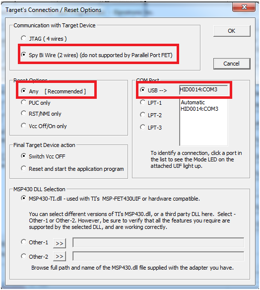
Go to Setup → Lock/ Unlock Setup and select Yes
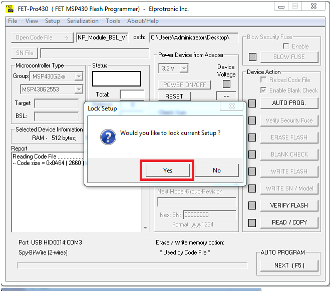
Press next to upload the boatloader to the MSP module
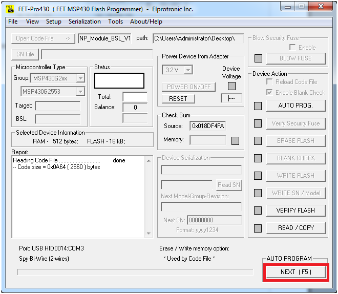
Wait until the process is finished and the status has updated to ‘Pass’
JS API Functions
addModuleType()
This is a list of functions used in Nexpaq API.
The addModuleType() function adds the specified module to the array of available modules.
Syntax
addModuleType(name, type_id)Parameters
name- The name that is to be assigned to the new Module.
type_id- A unique id that is assigned to the new module. .
Description
Use addModuleType() to add new modules to the list of available modules
addModuleTypes()
This is a description of the functions used in Nexpaq API
The addModuleType() method adds a group of modules to the array of available modules.
Syntax
addModuleTypes(array_of_names)
Parameters
array_of_names- A list of names that is to be assigned to the corresponding new modules.
Description
Use addModuleTypes() to add a group of new modules to the list of available modules.
hasModuleType()
This is a description of the functions used in Nexpaq API
The hasModuleType() method returns true if the specified module is present in the array of available modules.
Syntax
hasModuleType()
Return value
A boolean value.
Description
Use hasModuleType() to check if a module already exists in the array of available modules.
setCurrentModule()
This is a description of the functions used in Nexpaq API
The setCurrentModule() method sets the current module the API is working with and shows the header in the current module window.
Syntax
setCurrentModule(name)
Parameters
name- A name of the module that should be set as the current module.
Description
Use setCurrentModule() to set the current module.
Header functions
This is a description of the functions used in Nexpaq API for header
show()
The show() function inserts a pre-defined header to the current module with a back button to go back to the previous page .
Syntax
show()
Description
Use show() to insert a pre-defined header to the current module..
hide()
The hide() function hides the header. .
Syntax
hide()
Description
Use hide() to hide the header..
reset()
The reset() function removes the pre-defined header and show only the title of the header. .
Syntax
reset()
Description
Use reset() to remove the pre-defined header..
showTitle()
The showTitle() function shows the title of the header. .
Syntax
showTitle()
Description
Use showTitle() to show the title of the header..
hideTitle()
The hideTitle() function hides the title of the header. .
Syntax
hideTitle()
Description
Use hideTitle() to hide the title of the header..
disableButtons()
The disableButtons() function disables all the buttons present in the header . .
Syntax
disableButtons()
Description
Use disableButtons() to disable the buttons present in the header..
enableButtons()
The enableButtons() function enables all the buttons present in the header. .
Syntax
enableButtons()
Description
Use enableButtons() to enable the buttons present in the header..
cleanButtons()
The cleanButtons() function removes all the buttons present in the header.. .
Syntax
cleanButtons()
Description
Use cleanButtons() to remove all the buttons present in the header..
addButton()
The addButton() function adds a button and an image in the header. .
Syntax
addButton(icon,handler)
Parameters
icon- An image that should be sset as the button icon.
handler- An event handler called when the button is clicked.
Description
Use addButton() to add a button and an image in the header. icon is set as the button icon and handleris event handler called when that button is clicked..
hideBackButton()
The hideBackButton() function hides the back button. .
Syntax
hideBackButton()
Description
Use hideBackButton() to hides the back button present in the header.
showBackButton()
The showBackButton() function unhides the back button. .
Syntax
showBackButton()
Description
Use showBackButton() to unhides the back button present in the header.
setBackButtonIcon()
The setBackButtonIcon() function sets the specified image as the back button icon. .
Syntax
setBackButtonIcon(icon)
Parameters
icon- An image that should be set as the back button icon.
Description
Use setBackButtonIcon() to set the specified image as the back button icon.
Header functions
This is a description of the functions used in Nexpaq API for header
show()
The show() function inserts a pre-defined header to the current module with a back button to go back to the previous page .
Syntax
show()
Description
Use show() to insert a pre-defined header to the current module..
hide()
The hide() function hides the header. .
Syntax
hide()
Description
Use hide() to hide the header..reset()
The reset() function removes the pre-defined header and show only the title of the header. .
Syntax
reset()
Description
Use reset() to remove the pre-defined header..
showTitle()
The showTitle() function shows the title of the header. .
Syntax
showTitle()
Description
Use showTitle() to show the title of the header.
hideTitle()
The hideTitle() function hides the title of the header.
Syntax
hideTitle()
Description
Use hideTitle() to hide the title of the header..
disableButtons()
The disableButtons() function disables all the buttons present in the header .
Syntax
disableButtons()
Description
Use disableButtons() to disable the buttons present in the header..
enableButtons()
The enableButtons() function enables all the buttons present in the header.
Syntax
enableButtons()
Description
Use enableButtons() to enable the buttons present in the header..
cleanButtons()
The cleanButtons() function removes all the buttons present in the header.. .
Syntax
cleanButtons()
Description
Use cleanButtons() to remove all the buttons present in the header.
addButton()
The addButton() function adds a button and an image in the header.
Syntax
addButton(icon,handler)
Parameters
icon- An image that should be set as the button icon.
handler- An event handler called when the button is clicked.
Description
Use addButton() to add a button and an image in the header. icon is set as the button icon and handleris event handler called when that button is clicked..
hideBackButton()
The hideBackButton() function hides the back button.
Syntax
hideBackButton()
Description
Use hideBackButton() to hides the back button present in the header.showBackButton()
The showBackButton() function unhides the back button. .
Syntax
showBackButton()
Description
Use showBackButton() to unhides the back button present in the header.
setBackButtonIcon()
The setBackButtonIcon() function sets the specified image as the back button icon. .
Syntax
setBackButtonIcon(icon)
Parameters
icon- An image that should be set as the back button icon.
Description
Use setBackButtonIcon() to set the specified image as the back button icon.
callNativeFunction()
This is a description of the functions used in Nexpaq API
The callNativeFunction() function calls JS function registered by native application and passes string content to it.
Syntax
callNativeFunction(func, content)Parameters
func- The function in the native app to be called.
content- The string content to be passed to the function.
Description
Use callNativeFunction() to call JS function registered by native application and pass string content to it. If content is not string, this function serialises it to JSON string. If JS API is not available, it stores the command and executes it when API becomes available.
saveData()
This is a description of the functions used in Nexpaq API
The saveData() function saves data such as data set name, value, time, location and tags to cloud.
Syntax
saveData(name, value, time, location, tags)Parameters
name- A string indicating data set name.
value- A string value of data set.
time- A string indicating time.
location- An array of integers indicating longitude and latitude.
tags- An array of strings indicating tags for each data set.
Description
Use saveData() to saves data such as data set name, value, time, location and tags to cloud.
sendCommand()
This is a description of the functions used in Nexpaq API
The sendCommand() function sends command to the hardware module through the JS API.
Syntax
sendCommand(command, options)Parameters
command- A string name to be sent to the hardware through JS API.
options- An array of integers.
Description
Use sendCommand() to send command to the hardware module through the JS API. The function uses ‘OnControl’ function in the JS API to send command name and array of integers to hardware.
requestDataStrings()
This is a description of the functions used in Nexpaq API
The requestDataStrings() function requests data strings from Native app.
Syntax
requestDataStrings(ids)Parameters
ids- An array of data ids to be retrieved.
Description
Use requestDataStrings() to request data strings from Native app.
saveDataString()
This is a description of the functions used in Nexpaq API
The saveDataString() function saves string in native apps memory.
Syntax
saveDataString(id, data)Parameters
id- A string representing unique id for the data string.
data- A string representing data content.
Description
Use saveDataString() to save string in native apps memory.
sendGlobalDataQuery()
This is a description of the functions used in Nexpaq API
The sendGlobalDataQuery() function sends a query to from phone to device requesting data but is independent of the user.
Syntax
sendGlobalDataQuery(name, options)Parameters
name- A string name indicating data set name.
options- An object representing data query options.
Description
Use sendGlobalDataQuery() to send a query to from phone to device requesting data but is independent of the user.
sendDataQuery()
This is a description of the functions used in Nexpaq API
The sendDataQuery() function sends a query to from phone to device requesting data.
Syntax
sendDataQuery(name, options)Parameters
name- A string name indicating data set name.
options- An object representing data query options.
Description
Use sendDataQuery() to send a query to from phone to device requesting data.
sendLocationRequest()
This is a description of the functions used in Nexpaq API
The sendLocationRequest() function requests current device location from user device.
Syntax
sendLocationRequest(name, options)Description
Use sendLocationRequest() to request current device location from user device.
addEventListener()
This is a description of the functions used in Nexpaq API
The addEventListener() function adds event handler for an event in the module.
Syntax
addEventListener(module, event_name:, func:)Parameters
module- A string representing the module to set event on.
event_name:- A string representing the event name.
func:- A string representing the function name to call on event.
Description
Use addEventListener() to add event handler for an event in the module.
void_np_api_setup()
This is a description of the functions used in Nexpaq firmware
The void_np_api_setup() function initializes pins and sets pin modes and values.
Syntax
void_np_api_setup()Parameters
null
Description
Use void_np_api_setup() to initializes pins and sets pin modes and values. ‘Setup’ loop will just run one time after powering the MSP. It also sets code’s version (optional)
closeApplication()
This is a description of the functions used in Nexpaq API
The closeApplication() function closes the current application.
Syntax
closeApplication()Description
Use closeApplication() to close the current application.
confirm()
This is a description of the functions used in Nexpaq API
The confirm() function alerts the user with a message and two buttons.
Syntax
confirm(title, message, first_button, second_button)Parameters
title- A string representing the tite of the message.
message- A string representing the message to be displayed to the user.
first_button- Text to be displayed on the first button.
second_button- Text to be displayed on the second button.
Description
Use confirm() to alert the user with a message and two buttons (such as “ok” and “cancel”).
alert()
This is a description of the functions used in Nexpaq API
The alert() function alerts the user with a message and a single button.
Syntax
alert(title, message, button)Parameters
title- A string representing the tite of the message.
message- A string representing the message to be displayed to the user.
button- Text to be displayed on the button.
Description
Use alert() to alert the user with a message and a single button (such as “ok”).
updateTile()
This is a description of the functions used in Nexpaq API
The updateTile() function allows the developer to share data for tile update
Syntax
updateTile(data)Parameters
data- An object of data for tile update.
Description
Use updateTile() to share data for tile update.
shareData()
This is a description of the functions used in Nexpaq API
The shareData() function allows developer to share data
Syntax
shareData(text,image)Parameters
text- A string representing the text to share.
image- A base64 encoded image.
Description
Use shareData() to share data
triggerNativeEvent()
This is a description of the functions used in Nexpaq API
The triggerNativeEvent() function calls an event from native app.
Syntax
triggerNativeEvent(event_name)Parameters
event_name- A string representing the name of event to call.
Description
Use triggerNativeEvent() to call an event from native app. Any function associated with the event is also executed.
addNativeEventListener()
This is a description of the functions used in Nexpaq API
The addNativeEventListener() function binds a function of one or more devices to a common event.
Syntax
addNativeEventListener(module, event_name, function_name, devices)Parameters
module- A string representing the current module.
event_name- A string representing the event name.
function_name- A string representing the name of function.
devices- An array of string representing the UUIDs of devices.
Description
Use addNativeEventListener() to bind a function of one or more devices to a common event.
addNativeEvent()
This is a description of the functions used in Nexpaq API
The addNativeEvent() function defines new event inside module.
Syntax
addNativeEvent(module, event_title, event_name)Parameters
module- A string representing the module to add event.
event_title- A string representating the title of event.
event_name- A string representing the event name.
Description
Use addNativeEvent() to define new event inside module. This function can not be used to redefine an existing event.
triggerEvent()
This is a description of the functions used in Nexpaq API
The triggerEvent() function triggers library event.
Syntax
triggerEvent(module, event_name, args)Parameters
module- A string representing the module to set event on.
event_name- A string representing the event name.
args- An array of arguments to pass to the event handlers.
Description
Use triggerEvent() to trigger library event.